Hydrophone housing

a hydrophone and sensing element technology, applied in the field of hydrophone housings, can solve the problems of incomparable measured signals, disadvantages of prior art hydrophones for sensing pressure changes, and inability to detect pressure changes, so as to reduce absolute strain in the element, increase the sensitivity, and reduce the effect of compliance of the sensitive par

Active Publication Date: 2015-03-26
OPTOPLAN
View PDF12 Cites 2 Cited by
  • Summary
  • Abstract
  • Description
  • Claims
  • Application Information

AI Technical Summary

Benefits of technology

[0032]Analogously to the pressure balancing of the housing as described above, the internal volume of the hydrophone sensing element may also be liquid-filled and DC pressure balanced. This is an advantage for applications under large hydrostatic pressures, i.e. deep water. By pressure balancing the hydrophone sensing element, the sensitive part may be made thinner as it does not need to be dimensioned to withstand a large pressure difference. Thus, the compliance of the sensitive part may be significantly increased, hence increasing the sensitivity, while still allowing for use in deep water. A further advantage of pressure balancing the hydrophone sensing element is that the absolute strain in the element may be reduced. In a fibre-optic mandrel hydrophone sensing element, this reduces the requirement on fibre strain when spooling the fibre onto the mandrel, thus improving the reliability of the device. Pressure balancing of the hydrophone sensing element may be achieved by connecting the internal volume of the hydrophone sensing element with the inner chamber via an internal equalizing duct. The internal equalizing duct must be dimensioned so that only low frequency pressure variations may pass the duct. Thus, similar design objectives apply to the internal equalizing duct as to the second duct.
[0033]In an embodiment of the invention, the hydrophone housing further comprises an accelerometer chamber adapted for housing at least a first accelerometer, such as three accelerometers. In this way, the hydrophone housing may act as a complete sensor station, e.g. in a 4-component (4C) sensor system, comprising x-,y-,z-accelerometer and the hydrophone sensing element. For a discussion on different configurations of such 4C sensor stations, please refer to U.S. Pat. No. 7,551,517 by the same application, which is hereby incorporated by reference for the purpose of describing sensor station layouts. The accelerometer chamber may be in fluid communication with the inner chamber, the outer chamber or the first duct via a connection duct. Thus, the accelerometer chamber is preferably DC balanced with the inner and outer chambers, and optionally with the distensible equalizing chamber, but does not receive the acoustic pressure variances from the outer chamber. In this way, a particularly efficient and integrated sensor station may be achieved, which is fully pressure balanced and thus alleviates the need for pressure sealings. Furthermore, the sensors of the sensor station may be formed by a continuous length of optical fibre, due to the reduced requirements on strain tolerance and pressure sealing.

Problems solved by technology

This imposes a number of challenges.
When the hydrophone is buried in materials with significant shear stiffness, pressure changes to be measured will in addition to cause strain in the sensing element, also cause elastic stress in the surrounding sediments close to the sensing element.
These elastic stresses will restrict deflection of the surrounding sediments, and thus potentially reduce the resulting strain in the sensing element, i.e. cause loss in the acoustic pressure energy transfer.
The prior art hydrophones are therefore disadvantageous for sensing pressure changes in materials of uncertain or varying shear stiffness.
Since the properties of sediments may vary over time as well as with location, the pressure transfer to buried hydrophones, and thus the measured signals, becomes incomparable.
Secondly, the hydrophone is subject to a rough handling during burying leading to the need for a stronger protection than required for hydrophones used in water.

Method used


Image

  • Hydrophone housing
  • Hydrophone housing
  • Hydrophone housing

Examples


Embodiment Construction

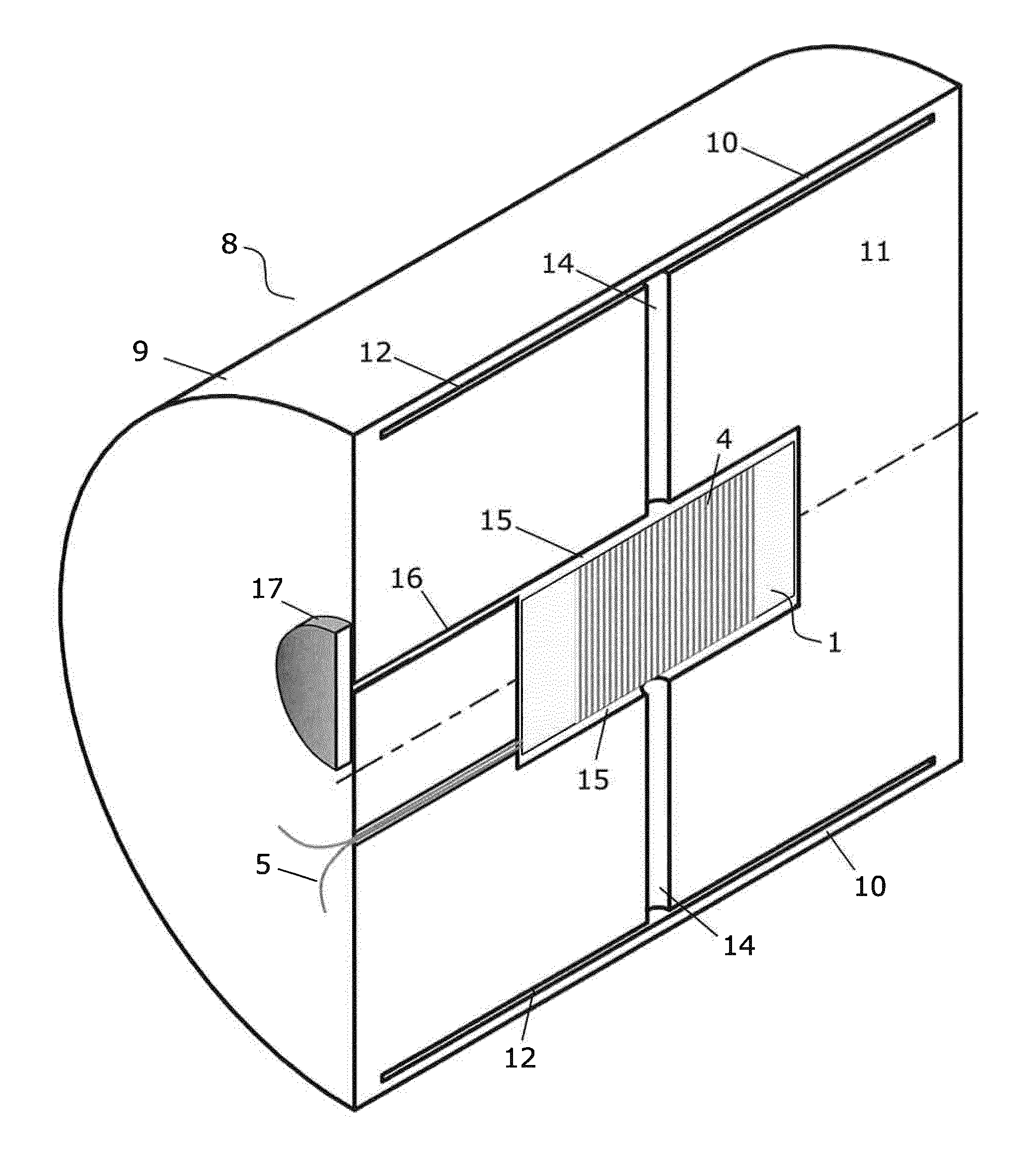
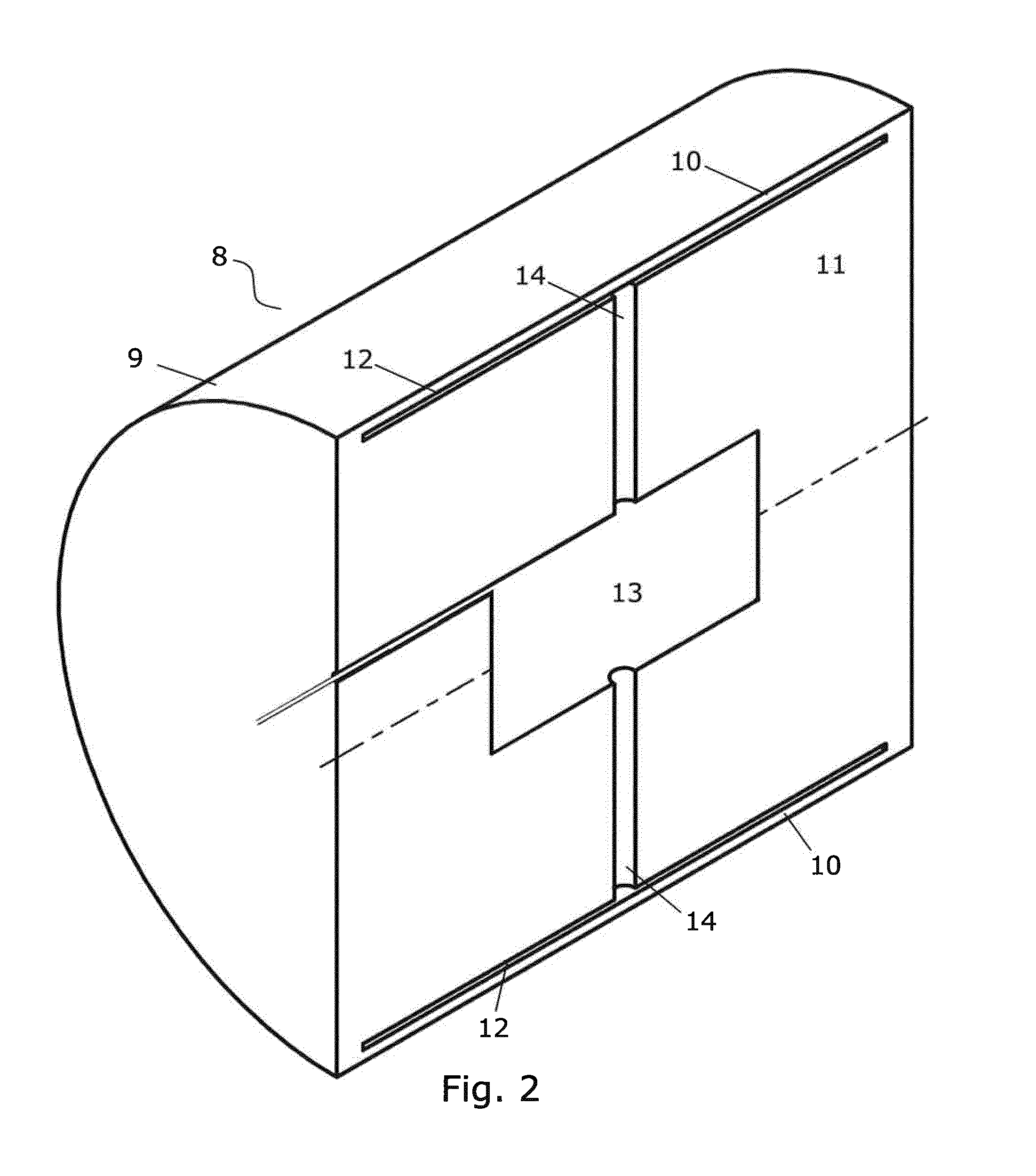
[0046]FIG. 2 illustrates an embodiment of a hydrophone housing 8 according to the invention. The housing comprises an outer casing 9 having an exterior shape suitable for being in close contact with sediment when buried therein. The casing is preferably made in metal, such as stainless steel.

[0047]Part of the casing is very thin in order to form a deflectable wall part 10. As previously mentioned, the area (A1) and thickness of the flexible wall part, as well as the material of the casing, are selected to achieve the desired acoustic pressure transfer properties. The interior of the casing is partly filled with a substantially incompressible solid material 11, typically also metal, such as stainless steel. It is important that this material does not absorb pressure energy, as that would devaluate the acoustic pressure transfer to the hydrophone sensing element 1. The solid material is arranged so that it defines at least:[0048]an outer chamber 12 behind the deflectable wall part;[00...


PUM


Abstract

The invention relates to a hydrophone housing. The housing comprises an outer casing with an exterior shape being in close contact with sediment when buried therein and having a deflectable wall part. Solid material partly fills the casing to define an outer chamber behind the deflectable wall part, a cavity shaped so that an inner chamber is defined immediately surrounding a hydrophone sensing element held therein, and a first duct for liquid flow communication between the outer chamber and the cavity or an internal volume of the hydrophone sensing element. Thereby, a hydraulic coupling is provided so that an acoustic pressure causing small radial displacements of outer surface of the housing will, via liquid in the first duct, cause large radial displacements of the hydrophone sensitive element. The area of the deflectable wall part is much larger than the area of the sensitive element so that only small displacements of the housing are required to cause large displacements at the hydrophone sensing element.

Description

FIELD OF THE INVENTION[0001]The present invention relates to a housing for a hydrophone sensing element, in particular for a hydrophone sensing element to be buried in sediment.BACKGROUND OF THE INVENTION[0002]A hydrophone generally involves the following elements: a hydrophone sensing element for generating a signal when subject to pressure changes connected to means for acquiring or transmitting the signal, including a support structure for holding these and optionally shielding for protection of the hydrophone sensing element.[0003]FIG. 1 is a schematic illustration of a hydrophone sensing element, here a fibre-optic air-backed mandrel hydrophone 1. The support structure is here provided by mandrel 2 around which an optic fibre 3 is coiled. The sensitive part of the hydrophone sensing element is here the surface part 4 which is typically cylindrical. The mandrel is mounted on an inner tube 6 to form an air or gas filled cavity in between to make the sensitive element air-backed. ...

Claims


Application Information

Patent Timeline
Patent Type & Authority Applications(United States)
IPC IPC(8): G01V1/18
CPCG01V2210/1427G01V1/188G01H9/004G01V1/186G01V1/189
Inventor FURUHAUG, ROARKRINGLEBOTN, JON THOMAS
Owner OPTOPLAN
Why Eureka
Try Eureka