Laminated film

a laminated film and film roll technology, applied in the field of laminated film and film roll, can solve the problems of difficult to obtain a large area, inability to obtain a sheet, etc., and achieve the effects of uniform optical properties, low cost, and large area

Active Publication Date: 2015-03-26
TORAY IND INC
View PDF2 Cites 5 Cited by
  • Summary
  • Abstract
  • Description
  • Claims
  • Application Information

AI Technical Summary

Benefits of technology

[0011]In view of the above-described problems associated with conventional techniques, the present invention provides a width-direction multilayer laminated film having a large area and uniform optical properties. The present invention also provides a light guide, a light diffusion film, a light-collecting film, a viewing angle control film, and an optical waveguide film, which are low cost and have excellent optical properties, and an illuminating device, a communication device and a display using these films.
[0013]The laminated film of the present invention can be a width-direction multilayer laminated film having a large area and uniform optical properties. Since a width-direction multilayer laminated film having a large area can be obtained, the film can be manufactured at very low cost. Further, in an embodiment of a film whose part of end portion is branched, it is easy to connect the film to an illuminating device.

Problems solved by technology

It is, however, not possible to obtain a sheet which has a large area and a uniform performance by this method.
This is because disappearance of a layer, unification of layers or the like is caused by a considerable flow disturbance due to repeated deformations by a mixer or a deformation through an extrusion die when a very large number of layers each having a minute width are to be obtained by the mixer method.
In this method, a width-direction multilayer laminated film with a higher precision compared with a film obtained by a method in which a mixer is employed, can be obtained; however, the upper limit of the substantial number of the layers aligned in a line is 301, the shape, position and cross section area of the core layer is hard to be stable due to the configuration of the die and therefore, and it was difficult to obtain a width direction multilayer laminated film having a large area.Patent Literature 1: JP 2001-91708 APatent Literature 2: JP 51-33177 APatent Literature 3: JP 2006-221145 A

Method used


Image

  • Laminated film
  • Laminated film
  • Laminated film

Examples


example 1

[0146]The following resin A and resin B were provided.

[0147]Resin A: Polypropylene (PP)

[0148]Polypropylene Noblen WF836DG manufactured by Sumitomo Chemical

[0149]Resin B: Polycarbonate (PC)

[0150]Polycarbonate LC1700 manufactured by Idemitsu Kosan

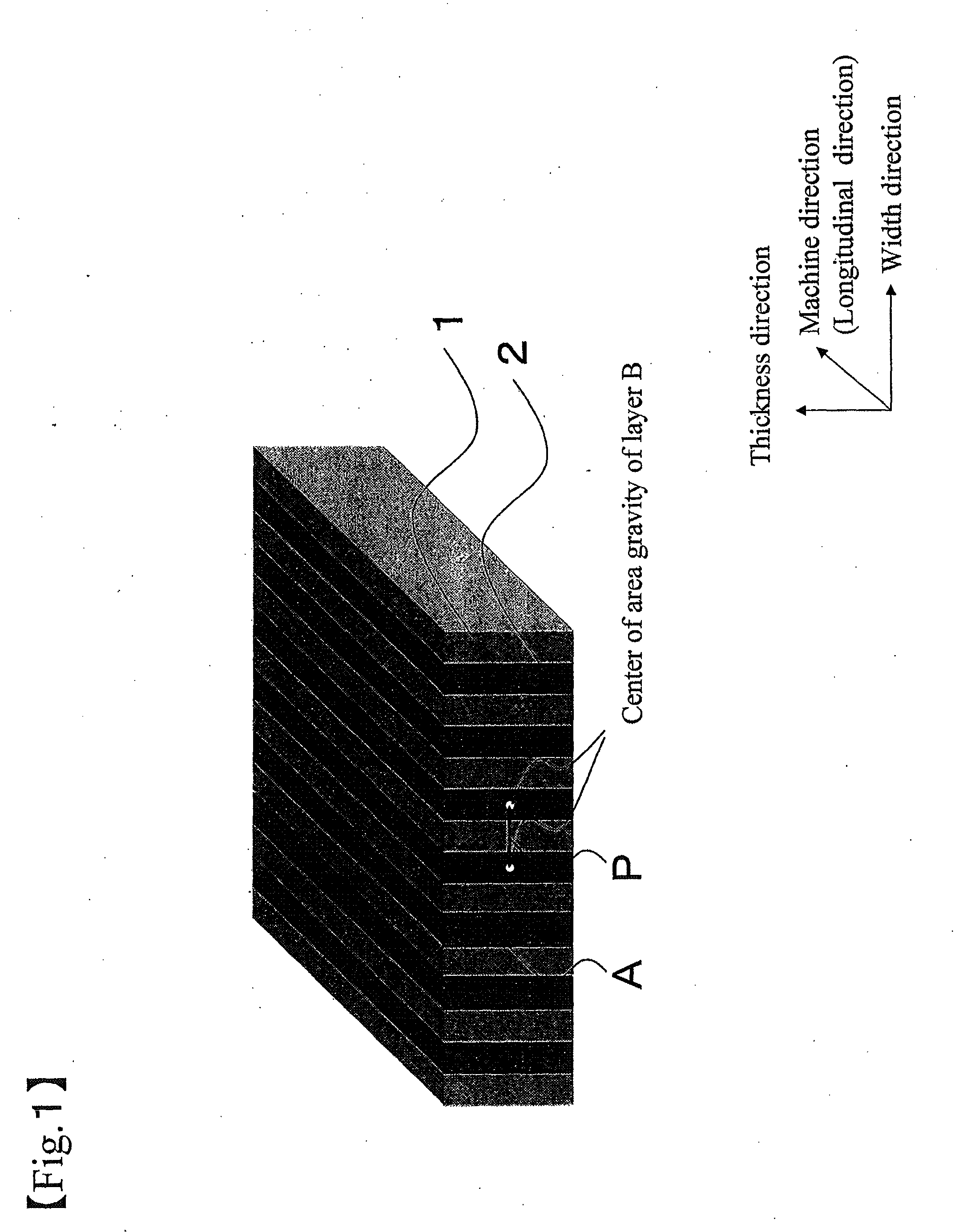
[0151]Then resin A was fed to an extruder 1 and resin B was fed to an extruder 2. The resins were melted in the respective extruders at 280° C., and were flown into an extrusion die 700 mm wide as shown in FIGS. 3 to 5 after passing through a gear pump and a filter. The extrusion die was provided with 600 rectangular nozzles, through which the resin B flew. The sheet from the extrusion die was nip-cast on a drum maintained at a temperature of 80° C. while being engaged at the end portions thereof with edge guides. The resultant was then cut off by 45 mm at both end portions and wound with a winder without causing an oscillation. Next, the resultant was wound with a slitter while being subjected to a knurling-process and laminated with a prote...

example 2

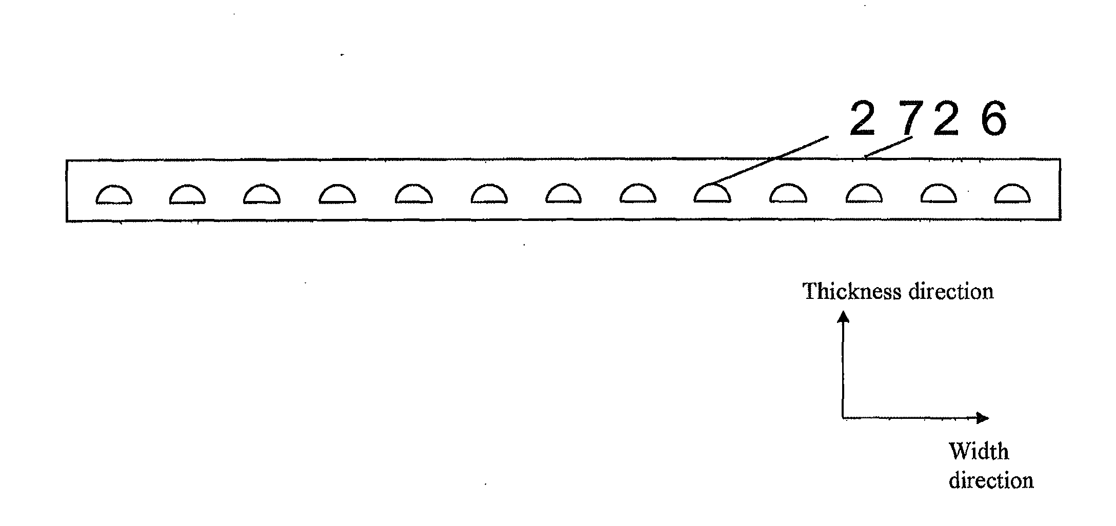
[0152]A film was prepared under substantially the same conditions as in Example 1 except that the extrusion die used was 1900 mm wide and provided with 1800 nozzles and that the discharge rate was adjusted. The film obtained had a thickness of 1000 μm (excluding the protective film). Resin B was arranged successively in the longitudinal direction and at substantially regular intervals of 1 mm±0.09 mm in the width direction, forming the structure in which the resin B was covered with resin A. The cross-sectional shape of the resin B was substantially circular and there were 1800 pieces of the resin B with a cross-sectional width of 800 μm±9 μm. Table 1 shows the structure and performance of the laminated film obtained. The film obtained was able to transmit light with a small loss and therefore suitable for an optical waveguide, a light guide and an illumination apparatus.

example 3

[0153]The following resin A and resin B were provided.

[0154]Resin A: Polycarbonate (PC)

[0155]Polycarbonate LC1700 manufactured by Idemitsu Kosan

[0156]Resin B: Polycarbonate (PC)+carbon black (CB) 2 wt %

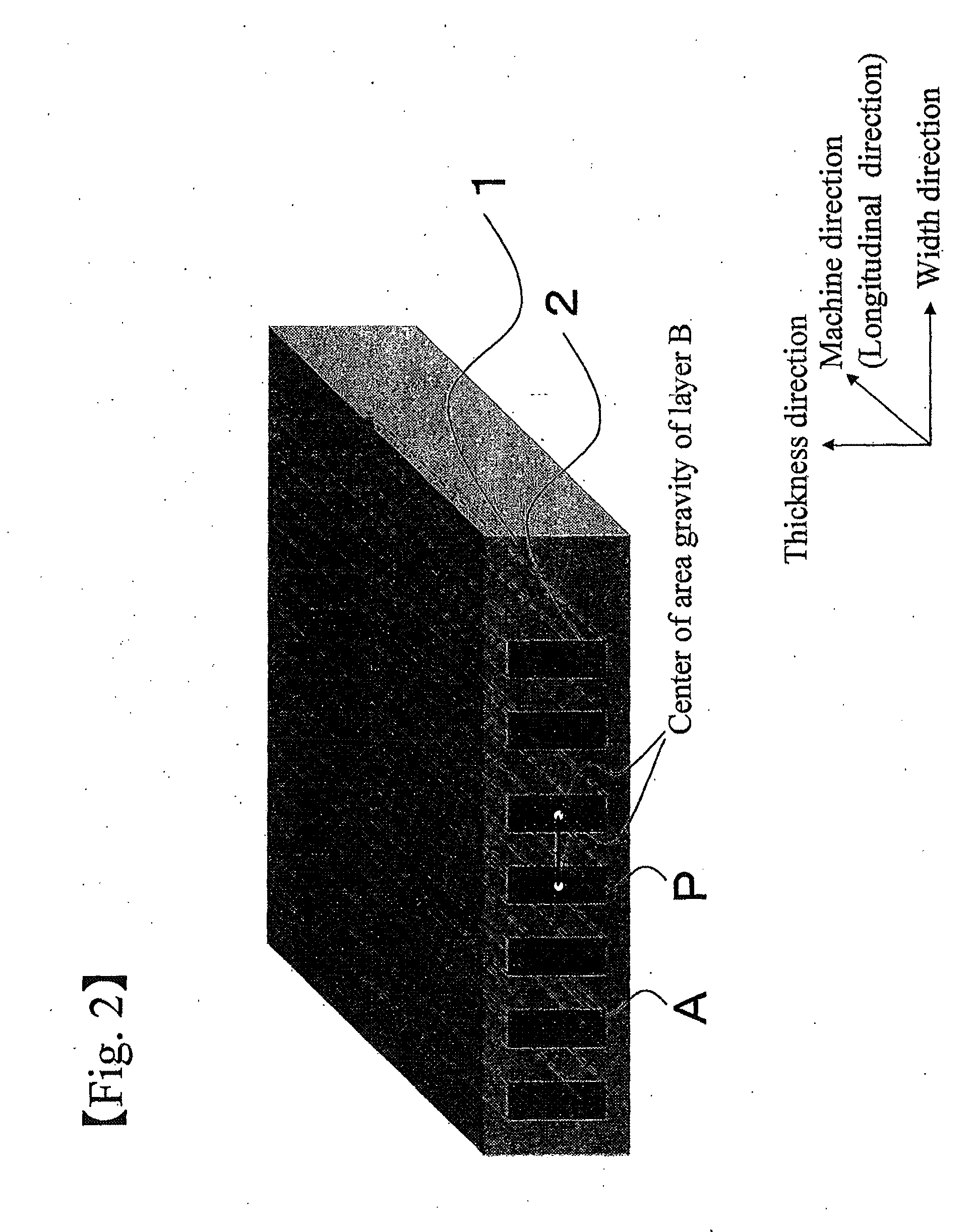
[0157]Then resin A was fed to an extruder 1 and resin B was fed to an extruder 2. The resins were melted in the respective extruders at 290° C., and were flown into an extrusion die 700 mm wide as shown in FIGS. 3 to 5 after passing through a gear pump and a filter. The extrusion die was provided with 3000 rectangular nozzles that were longer in the thickness direction than in Example 1, through which the resin B flew. The sheet from the extrusion die was nip-cast on a drum maintained at a temperature of 80° C. while being engaged at the end portions thereof with edge guides. The resultant was then cut off by 45 mm at both end portions and wound with a winder without causing an oscillation. Next, the resultant was wound with a slitter while being subjected to a knurling-process and la...


PUM

PropertyMeasurementUnit
widthaaaaaaaaaa
widthaaaaaaaaaa
widthaaaaaaaaaa

Abstract

A width-direction multilayer laminated film having a large area and uniform optical properties is provided. A light guide, a light diffusion film, a light collecting film, a viewing angle control film, and an optical waveguide film, which are low cost and have excellent optical properties, as well as an illuminating device, a communication device, and a display using these films. The laminated film may include at least a structure in which a layer made of resin A (layer A) and a layer made of resin B (layer B) are alternately laminated in the width direction, wherein the width of the film is 400 nm or more and the number of layer Bs, each having a cross-sectional width from 0.1 μm to 10,000 μm, is 10 or larger.

Description

CROSS-REFERENCE TO RELATED APPLICATIONS[0001]This application is a is a divisional application of U.S. patent application Ser. No. 12 / 921,982, filed Sep. 10, 2010, which is the U.S. National Phase Application of PCT International Application No. PCT / JP2009 / 053908, filed Mar. 3, 2009, which claims priority to Japanese Patent Application No. 2008-065317, filed Mar. 14, 2008, the contents of each of these applications being incorporated by reference herein in their entirety.TECHNICAL FIELD[0002]The present invention relates to a laminated film and a film roll thereof. The present invention also relates to a film suitable for a light guide, a light diffusion film, a light-collecting film, a viewing angle control film, an optical waveguide film and the like, and to an illuminating device, a communication device, a display and the like using the same.BACKGROUND OF THE INVENTION[0003]A backlight display has become widespread in which a liquid crystal layer is illuminated from the backside ...

Claims


Application Information

Patent Timeline
Patent Type & Authority Applications(United States)
IPC IPC(8): B29C47/30B29C47/06B29C48/08B29C48/305B29C48/345
CPCB29C47/062B29C47/30B29C48/08B29C48/30B29C48/21B29C48/307G02B5/0242G02B6/124B29C48/07G02F1/13363B29K2025/00B29K2067/043B29K2069/00B29K2067/046B29K2033/12G02B6/1221B29C48/345B29C48/19
Inventor UTO, TAKAYUKIOSADA, SYUNICHI
Owner TORAY IND INC
Why Eureka
Try Eureka