
Cardiac valve prosthesis

a heart valve and prosthesis technology, applied in the field of implantable cardiac prosthesis, can solve the problems of poor cardiac function, heart failure, inability to meet the body's demands, etc., and achieve the effect of reducing thrombosis and reducing thrombosis formation

Inactive Publication Date: 2015-03-26
SAN DIEGO STATE UNIV RES FOUND
View PDF7 Cites 2 Cited by
  • Summary
  • Abstract
  • Description
  • Claims
  • Application Information

AI Technical Summary

Benefits of technology

The patent describes a way to prevent blood clots in patients who have a ventricular assist device (VAD) and a closed aortic valve. This is done by inserting a prosthesis into the aortic root and attaching it to the closed valve. This reduces the risk of blood clots in the left ventricular outflow tract, which can help improve patient outcomes.

Problems solved by technology

Heart failure is characterized by poor cardiac function and the heart's inability to meet the body's demands.
Heart transplants are in limited supply and come with long waiting-lists, often months to years to find donor matches.
Although LVADs have been shown to significantly improve mortality and quality of life, the alteration of the blood flow pathway creates high-risk complications, such as thromboembolism.
Furthermore, persistent high transvalvular pressure across the aortic valve reduces its opening frequency, which tends to worsen any native aortic valve insufficiency.
However, prosthetic aortic valves are contraindicated in LVAD patients, leaving approximately 20% of patients with conditions warranting permanent closure of the aortic valve.
Surgical closure of the valve has demonstrated no adverse effects on mortality, but the closed pathway in the aortic root provides a greater risk for blood stasis, which may initiate thrombosis.
The current practice for valve closure surgery is to use pericardial strips or patches, which provide a secure closure, but are not systematically designed to produce a consistent, long-term result.

Method used


Image

  • Cardiac valve prosthesis
  • Cardiac valve prosthesis
  • Cardiac valve prosthesis

Examples


example 1

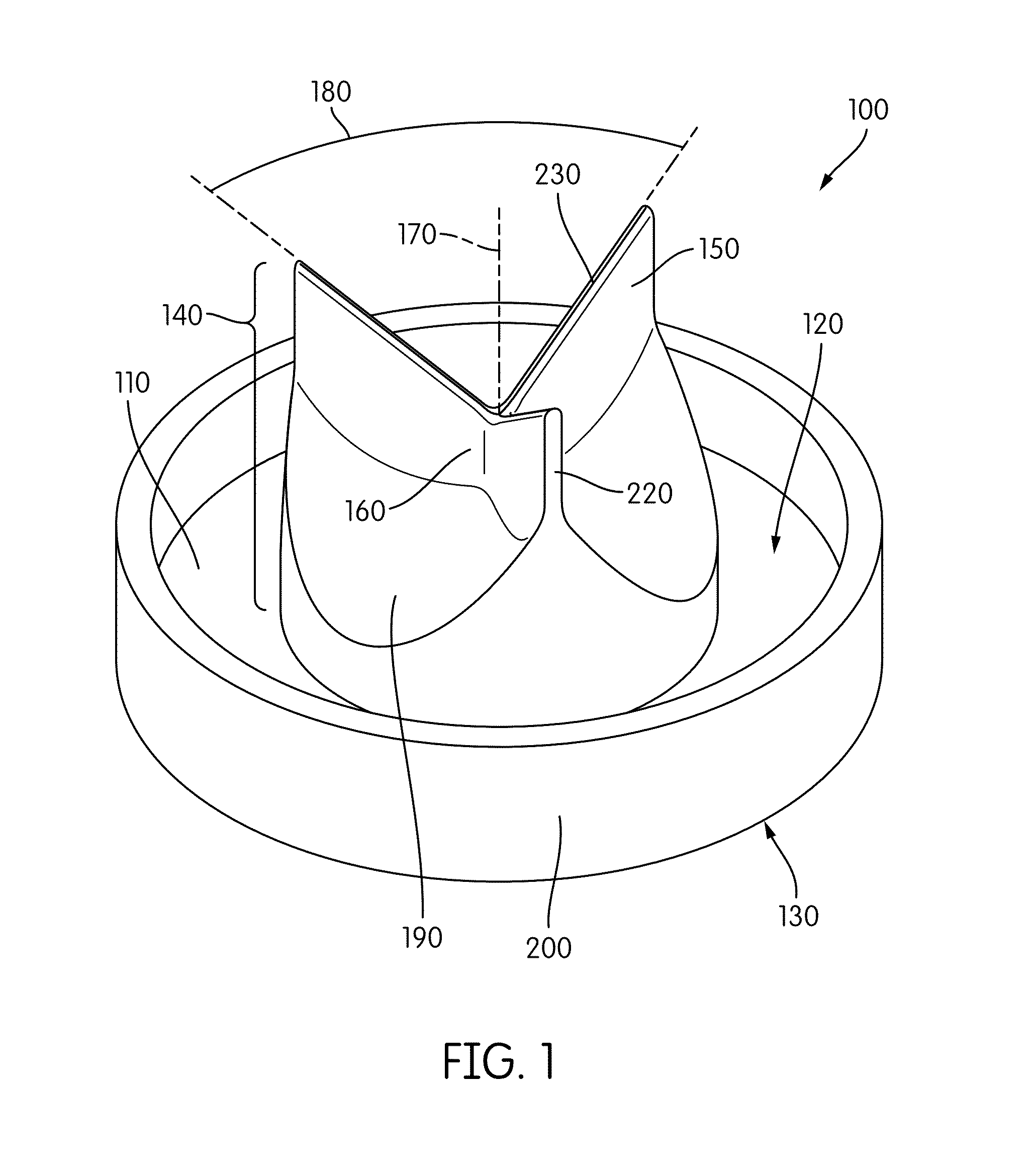
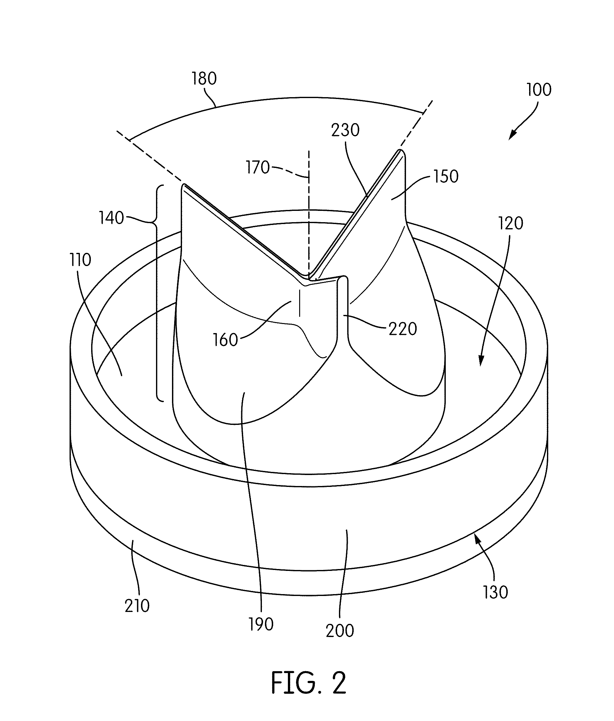
[0041]This study was designed to test the hypothesis that aortic valve closure surgery, as currently practiced, produces abnormal aortic root flow patterns that lack the sinus vortices and instead exhibit regions of stagnation that reduce aortic washout, and that a prosthesis shaped like the closed aortic valve and designed to fit over the aortic valve orifice will reestablish advantageous flow patterns such as sinus vortex formation, and result in a consistent and improved outcome compared with the current techniques. The aims of the study were to (1) quantitatively measure the flow field in the aortic root of a LVAD-assisted heart in a cardiac simulator using Digital Image Particle Velocimetry (DPIV), and (2) use this method to compare the circulation with two different prosthetic valve closure designs.

[0042]A mock circulatory loop, which included a glass aorta connected to an LVAD (HEARTMATE II LVAD, Throatec Corporation), was designed to simulate flow in the aorta while supporte...


PUM


Abstract

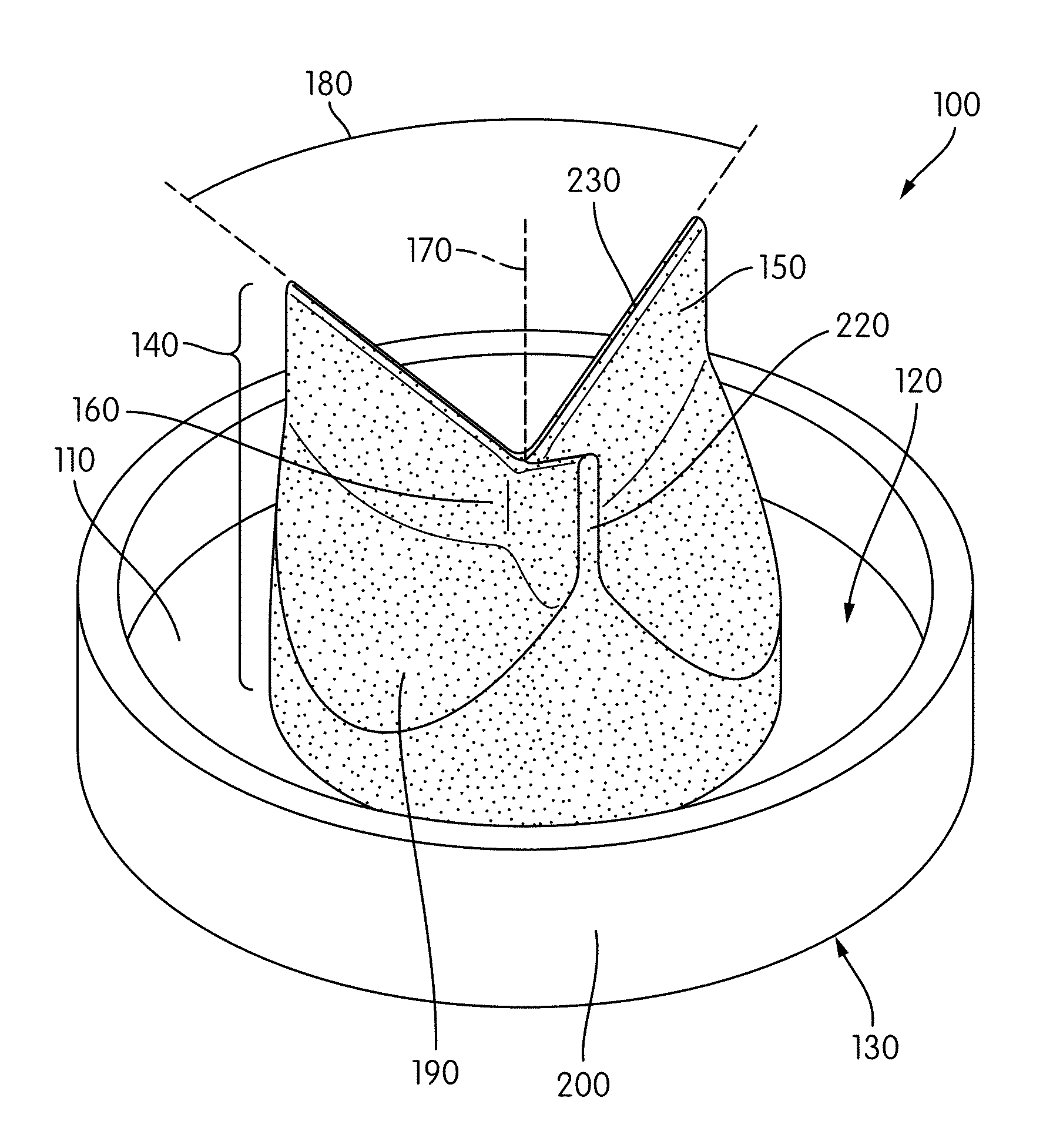
Provided herein is a prosthetic device in patients with ventricular assist device (VAD) support and a closed off aortic valve orifice, which reestablishes the formation of normal fluid flow patterns in the aortic root. The prosthesis includes a circular body having a first surface and a second surface and a projection disposed on the first surface of the body, wherein the projection includes a plurality of walls extending away from the first surface of the body, each wall being positioned such that a first side edge contacts a center of the body, thereby forming a plurality of intercepted arcs, each located between adjacent walls; and a plurality of concave parabolic surfaces, each disposed within an intercepted arc. Also provided are methods of using the prosthetic device to reduce thrombosis formation in patients with VAD support.

Description

CROSS REFERENCE TO RELATED APPLICATION(S)[0001]This application claims the benefit of priority under 35 U.S.C. §119(e) of U.S. Ser. No. 61 / 883,091, filed Sep. 26, 2014, the entire content of which is incorporated herein by reference.BACKGROUND OF THE INVENTION[0002]1. Field of the Invention[0003]The invention relates generally to an implantable cardiac prosthesis, and more specifically to a cardiac valve prosthesis used in aortic valve closure surgery to improve the flow pattern in the aortic root.[0004]2. Background Information[0005]Heart failure is a debilitating condition that affects approximately 5.8 million Americans. Heart failure is characterized by poor cardiac function and the heart's inability to meet the body's demands. Heart transplants are in limited supply and come with long waiting-lists, often months to years to find donor matches.[0006]Continuous flow left ventricular assist devices (LVADs) are implantable, mechanical pumps implanted to treat severe heart failure. ...

Claims


Application Information

Patent Timeline
IPC IPC(8): A61F2/24A61M60/178
CPCA61F2/2412A61F2/2475A61F2230/0067A61F2230/008A61F2250/0067A61M60/894A61M60/178
Inventor MAY-NEWMAN, KAREN
Owner SAN DIEGO STATE UNIV RES FOUND
Learn More