
Demand response method and demand response control apparatus

a demand response and control apparatus technology, applied in adaptive control, static/dynamic balance measurement, instruments, etc., can solve the problems of penalty charges and the possibility of penalties for dr providers, and achieve the effect of properly implementing multiple dr services

Active Publication Date: 2015-03-26
PANASONIC INTELLECTUAL PROPERTY MANAGEMENT CO LTD
View PDF3 Cites 34 Cited by
  • Summary
  • Abstract
  • Description
  • Claims
  • Application Information

AI Technical Summary

Benefits of technology

The invention allows for multiple drilling services to be implemented in a single step.

Problems solved by technology

On the other hand, the DR provider may face a penalty such as paying penalty charges to the DR aggregator when the DR provider fails to control the resource according to the DR service.

Method used


Image

  • Demand response method and demand response control apparatus
  • Demand response method and demand response control apparatus
  • Demand response method and demand response control apparatus

Examples


embodiment

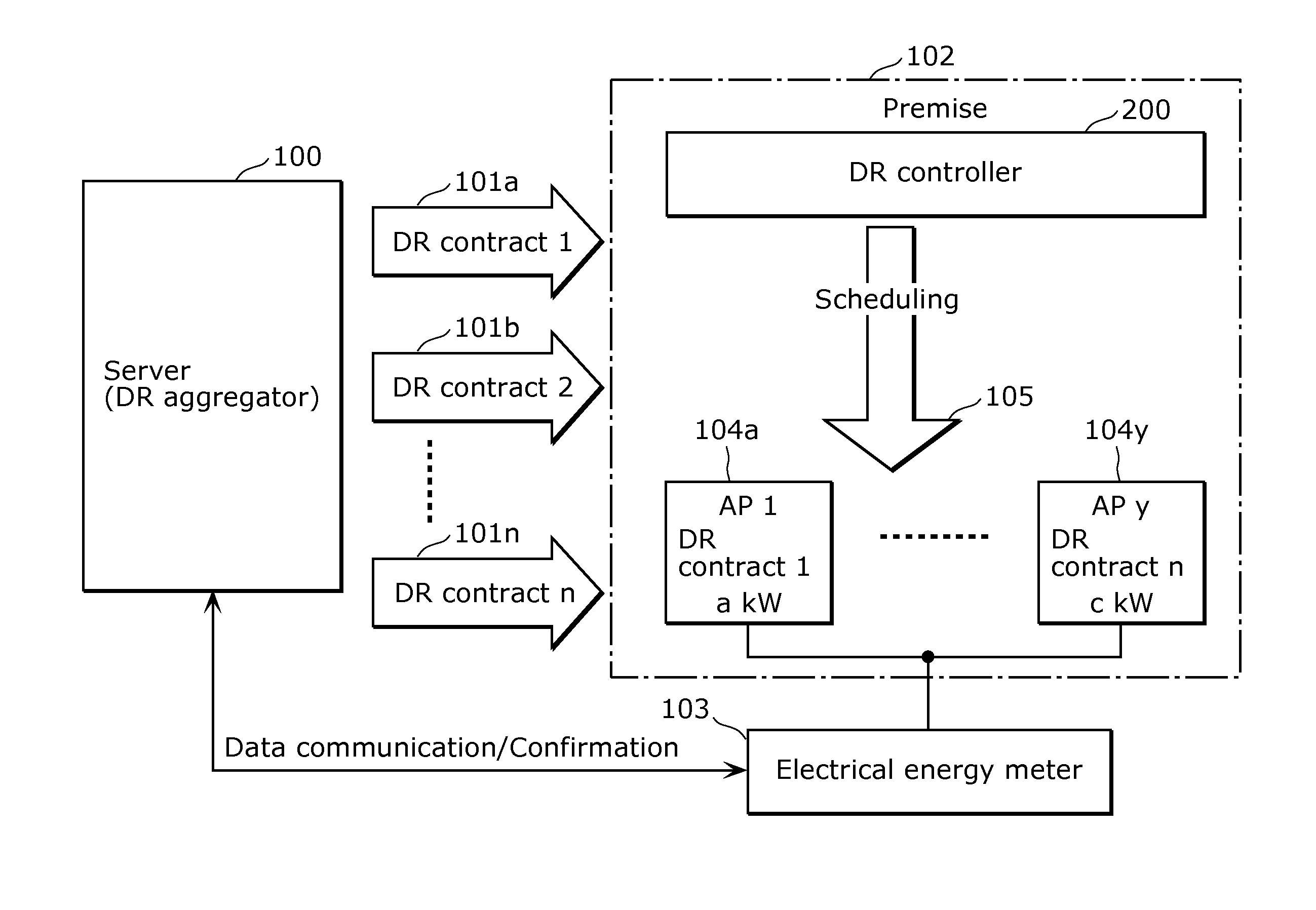
[0039]In this exemplary embodiment, an example of applying the demand response control apparatus according to the present invention to a DR controller provided in a premise managed by a DR provider will be described.

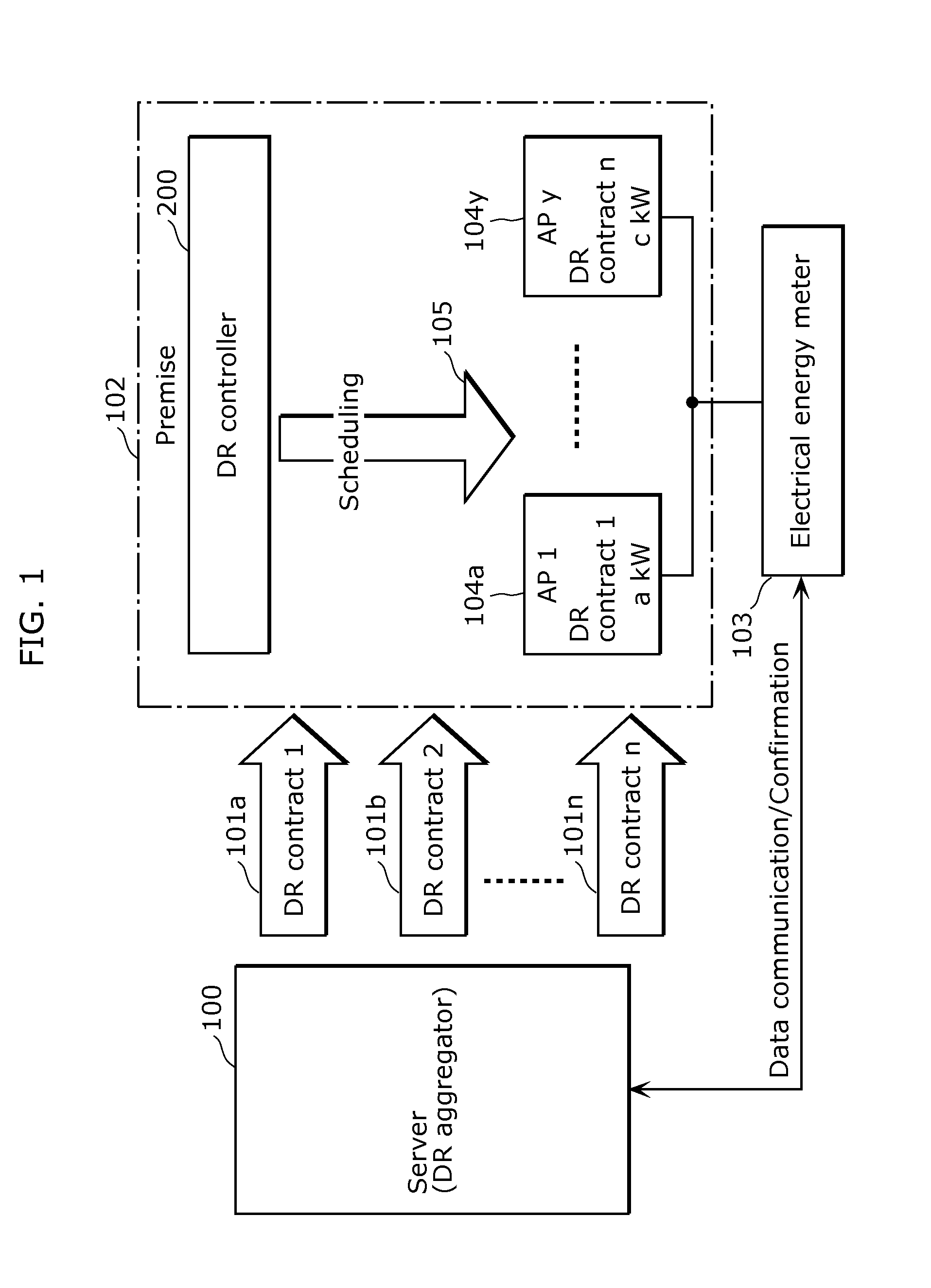
[0040]First, a system configuration of the DR system according to the exemplary embodiment will be described. FIG. 1 is a diagram illustrating a system configuration of the DR system according to the exemplary embodiment.

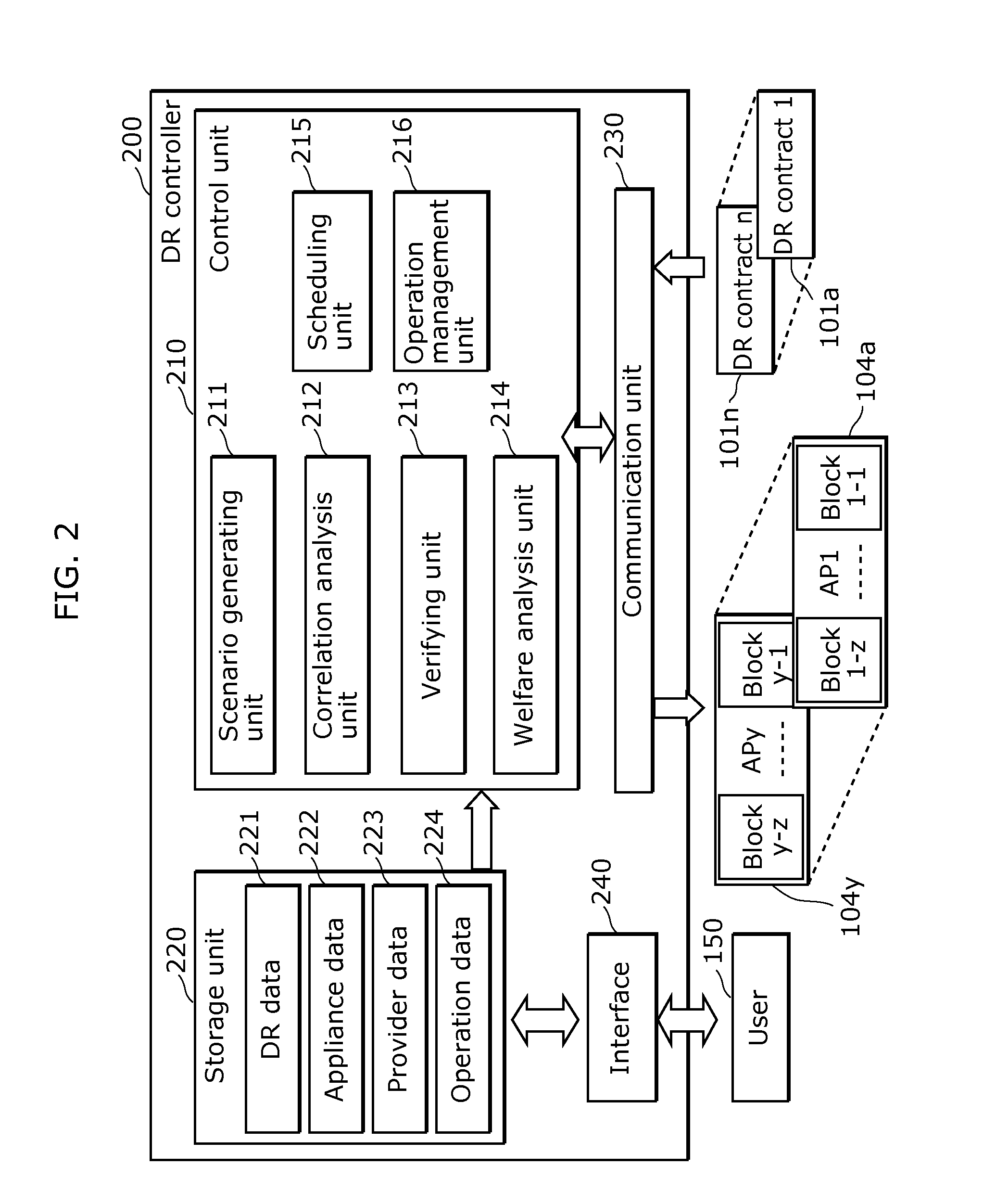
[0041]It is to be noted that an appliance is deemed as separate “control blocks” according to the state in this embodiment. For example, in the case of an air conditioner capable of switching the rated power among 75%, 50%, 25% and 0% to be allocated to a DR operation, this air conditioner is treated as four control blocks capable of performing the DR operation. More specifically, even though it is a single air conditioner, the state where 75% of the rated power can be used for the DR operation and the state where 50% of the rated power can be used for t...


PUM


Abstract

A demand response method includes: obtaining DR contracts scheduled to be implemented in a target period; determining, for each of the DR contracts, whether or not content of the adjustment of the supply and demand for electrical energy requested in the DR contract is executable; generating one or more DR scenarios each being a combination of two or more of the DR contracts executable in the target period; and extracting, from among the generated one or more DR scenarios, at least one DR scenario of which a total value of an amount of the adjustment of the supply and demand for electrical energy of the at least one appliance satisfies contract conditions of each of the two or more of the DR contracts included in the at least one DR scenario when the at least one appliance is caused to operate based on the at least one DR scenario.

Description

TECHNICAL FIELD[0001]The present invention relates to a demand response method and the like for adjusting supply and demand for electrical energy in an electrical energy system.BACKGROUND ART[0002]In recent years, due to tight condition of supply and demand for electrical energy and liberalization of the energy market, a demand response (hereinafter also referred to as “DR”) system has been receiving attention. In this DR system, there is a DR aggregator who provides a DR service to a customer. Based on a contract between the DR aggregator and the customer (hereinafter also referred to as “DR provider”), the DR aggregator requests the customer to adjust supply and demand for electrical energy in a predetermined period (time step), thereby adjusting the supply and demand for electrical energy in an electrical energy system (see Patent Literature (PTL) 1, for example).[0003]The DR provider controls a resource (an appliance which performs at least one of consuming electrical energy, ac...

Claims


Application Information

Patent Timeline
Patent Type & Authority Applications(United States)
IPC IPC(8): G05F1/66G05B15/02
CPCG05B15/02G05F1/66H02J3/008G06Q10/06Y04S50/10Y04S20/221Y02B70/30Y04S20/00Y04S20/222Y02B70/3225Y02B90/20H02J13/00002Y04S10/30Y02E60/00
Inventor BEHRANGRAD, MAHDI
Owner PANASONIC INTELLECTUAL PROPERTY MANAGEMENT CO LTD
Learn More