
Integrated magnetic circuit and method of reducing magnetic density by shifting phase

a technology of integrated magnetic circuit and phase, which is applied in the direction of electric variable regulation, process and machine control, instruments, etc., can solve the problems of increasing the power required for the ac adapter supplying power to these electronic devices, increasing costs, and increasing power consumption of mobile electronic devices in addition to notebook computers. achieve the effect of reducing volume and saving manufacturing costs

Inactive Publication Date: 2015-04-02
SOLUM CO LTD +1
View PDF4 Cites 4 Cited by
  • Summary
  • Abstract
  • Description
  • Claims
  • Application Information

AI Technical Summary

Benefits of technology

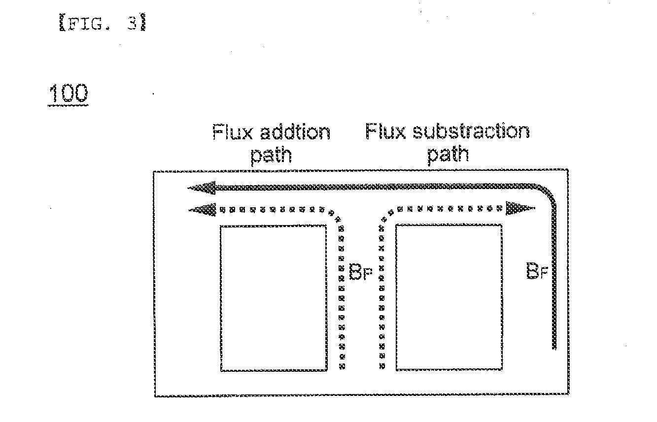
The patent is about a new design for a power factor correction circuit that reduces the size of the circuit and saves manufacturing costs. The design also prevents the magnetic flux from being saturated, which allows for a more efficient use of the circuit. The technical effect is a more compact and cost-effective power factor correction circuit that has improved performance.

Problems solved by technology

As power consumption of mobile electronic devices in addition to a notebook computer is increased, power required for an AC adapter supplying power to these electronic devices is increased.
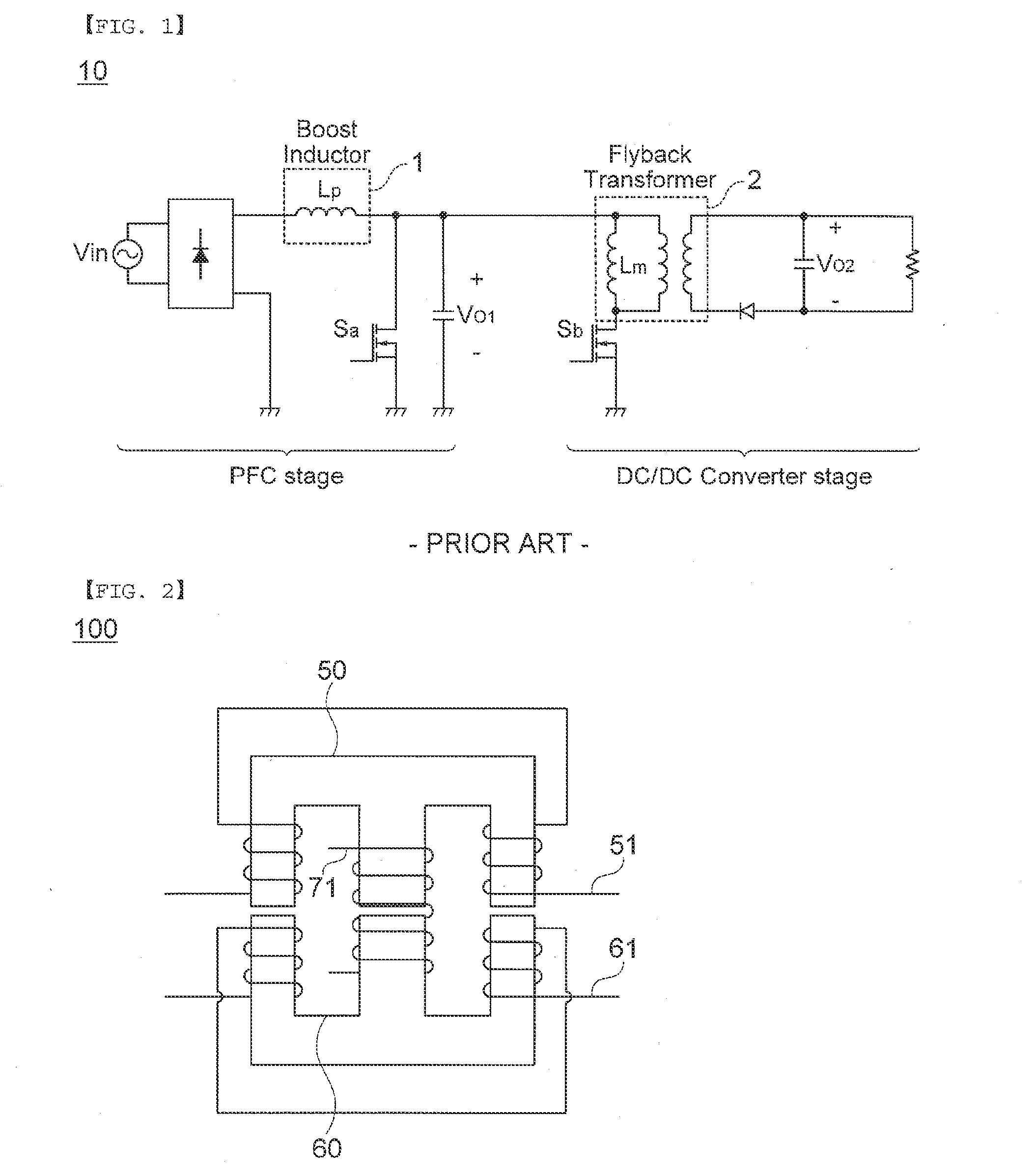
However, the two-stage scheme increases volume due to a PFC inductor and a DC / DC transformer and thus, increases costs.
However, a general power supply apparatus according to the related art that is disclosed in Patent Document 1 uses a separate transformer for implementing the PFC and the DC / DC converter or the DC / AC inverter, and the like and as a result, has a limitation in miniaturization.

Method used


Image

  • Integrated magnetic circuit and method of reducing magnetic density by shifting phase
  • Integrated magnetic circuit and method of reducing magnetic density by shifting phase
  • Integrated magnetic circuit and method of reducing magnetic density by shifting phase

Examples


Embodiment Construction

[0027]Hereinafter, exemplary embodiments of the present invention will be described in detail with reference to the accompanying drawings. However, this is only by way of example and therefore, the present invention is not limited thereto.

[0028]When technical configurations known in the related art are considered to make the contents obscure in the present invention, the detailed description thereof will be omitted. Further, the following terminologies are defined in consideration of the functions in the present invention and may be construed in different ways by the intention of users and operators. Therefore, the definitions thereof should be construed based on the contents throughout the specification.

[0029]As a result, the spirit of the present invention is determined by the claims and the following exemplary embodiments may be provided to efficiently describe the spirit of the present invention to those skilled in the art.

[0030]Hereinafter, exemplary embodiments of the present ...


PUM


Abstract

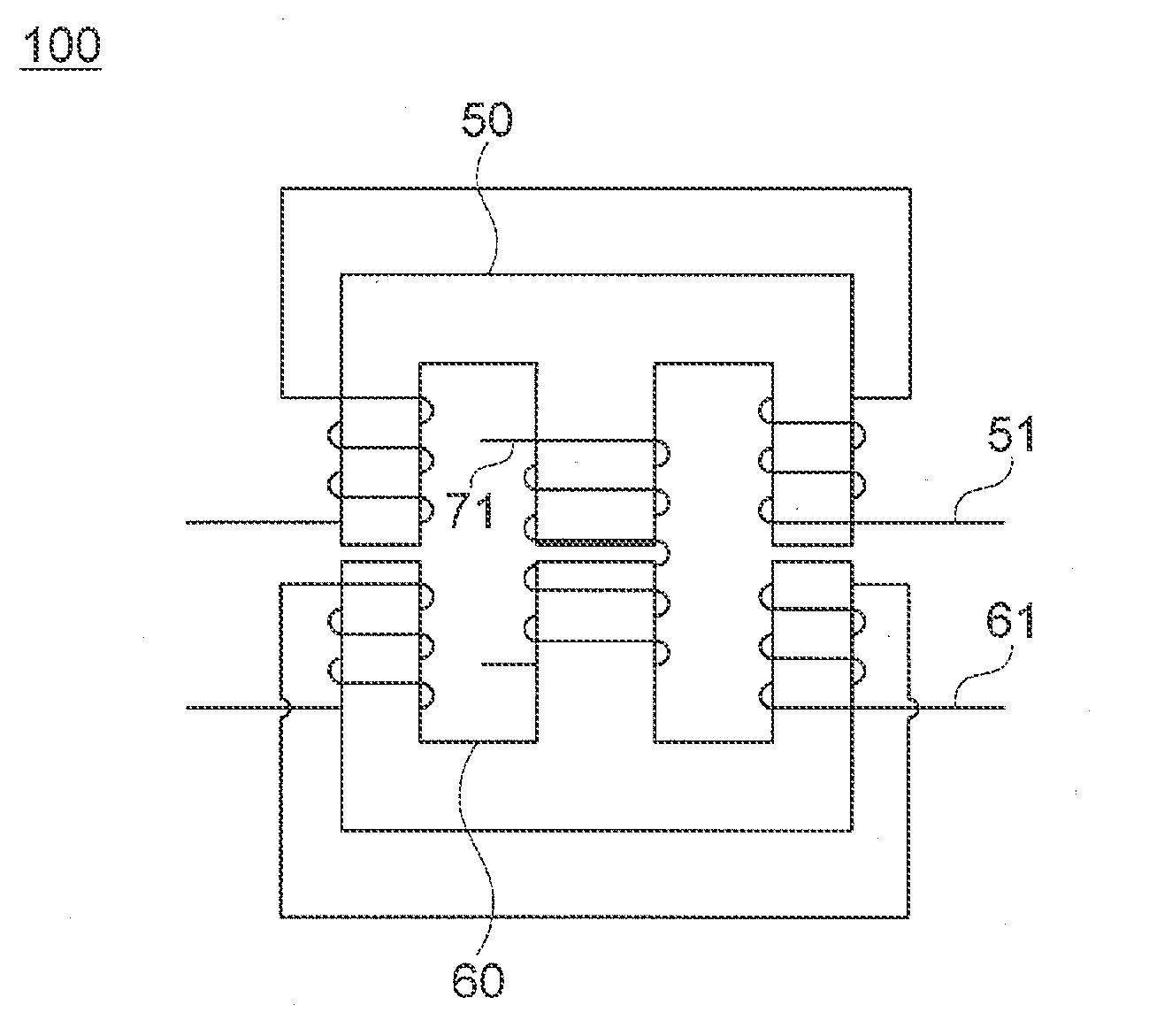
Disclosed herein are an AC-DC converter in which an inductor of boost PFC and a flyback transformer are integrated in one and a method of preventing a magnetic density from being saturated by shifting a phase. The integrated magnetic circuit according to an exemplary embodiment of the present invention includes: a power factor correction stage (PFC-stage) including a boost inductor; and a flyback transformer including a primary winding and a secondary winding, wherein the boost inductor and the primary winding of the flyback transformer and the secondary winding of the flyback transformer are wound around a single core.

Description

CROSS REFERENCE TO RELATED APPLICATIONS[0001]This application claims the benefit under 35 U.S.C. Section 119 of Korean Patent Application Serial No. 10-2012-0099877 entitled “Integrated Magnetic Circuit And Method of Reducing Magnetic Density By Shifting Phase” filed on Sep. 10, 2012, which is hereby incorporated by reference in its entirety into this application.BACKGROUND OF THE INVENTION[0002]1. Technical Field[0003]The present invention relates to an integrated magnetic circuit and method of reducing magnetic density by shifting a phase.[0004]2. Description of the Related Art[0005]As power consumption of mobile electronic devices in addition to a notebook computer is increased, power required for an AC adapter supplying power to these electronic devices is increased. The AC adapter needs to be miniaturized so as to be easily carried. As a result, increasing power density of the AC adapter is a main design point. Currently, components occupying the largest volume among components...

Claims


Application Information

Patent Timeline
IPC IPC(8): H02M1/42H02M3/335
CPCH02M3/33507H02M1/4208H02M1/40Y02B70/10H02M1/0064H01F27/28H01F38/42
Inventor WON, JAE SUNKIM, JONG HAESHIN, HWI BEOMLEE, YOUNG MINCHUNG, SE KYOKIM, SANG DAE
Owner SOLUM CO LTD
Learn More