Increasing eap conversion efficiency by continuous current

Active Publication Date: 2015-04-09
SINGLE BUOY MOORINGS INC
View PDF6 Cites 6 Cited by
  • Summary
  • Abstract
  • Description
  • Claims
  • Application Information

AI Technical Summary

Benefits of technology

The present invention is about a device that reduces energy loss and improves efficiency in the process of converting energy. It does this by using a special material that has very high resistance in one part of the device, while it has low resistance in another part. This results in a significant reduction in the ratio of effective current to average current, which reduces the amount of energy lost during the conversion process. Overall, this invention makes it possible to reduce energy waste and improve energy conversion.

Problems solved by technology

Given the high series resistance of present EAP devices, the energy lost in the charging and discharging phase easily exceeds the converted energy.
Therefore, high conversion efficiencies can only be achieved by a highly efficient charging and discharging process.

Method used


Image

  • Increasing eap conversion efficiency by continuous current
  • Increasing eap conversion efficiency by continuous current
  • Increasing eap conversion efficiency by continuous current

Examples


Embodiment Construction

[0034]The present invention proposes to significantly reduce the losses in the series resistances, both in the EAP based device and in other high-voltage components. The key in this invention is to optimize the conversion process at the place where the electrical conditions are poor, at the cost of a degraded conversion process at the place where the electrical conditions are (already) significantly better.

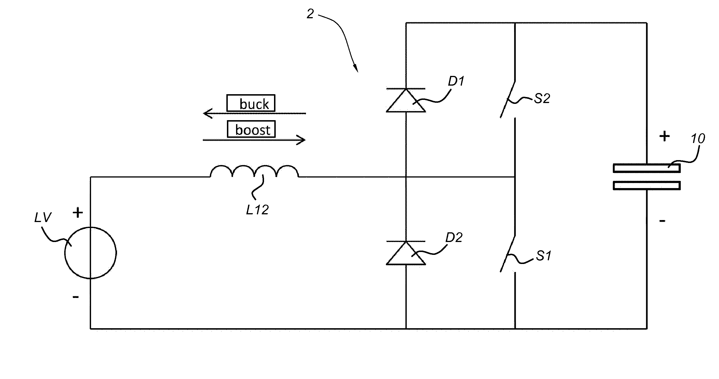
[0035]FIG. 2 shows schematically a part of a circuit of a prior art electromechanical energy conversion system 2 with a combined boost / buck converter between power source and EAP based device.

[0036]In this arrangement of the step-up converter and the step-down converter, the inductors of the step-up converter and the step-down converter are combined in a single inductor L12. Further, buck switching element S2 is now parallel with the boost diode D1, and the boost switching element S1 is now in parallel with the buck diode D2. The forward direction of the boost diode D1 is towards ...


PUM


Abstract

An electromechanical energy conversion system includes a variable capacitor, an electronic charging / discharging unit and a power source / sink; the power source / sink being coupled to the electronic charging / discharging unit which is coupled to the variable capacitor; the variable capacitor including first and second electrodes that are separated by an intermediate medium providing a gap distance therebetween; the gap distance being adjustable between a minimal distance and a maximal distance as a function of an externally applied mechanical force; the electronic charging / discharging unit being arranged for charging the variable capacitor from the power source / sink at substantially a state of the variable capacitor when the gap distance is minimal and the area of the elastically deformed body maximal, and for discharging the variable capacitor to the power source / sink at substantially a state of the variable capacitor when the gap distance is maximal and the area of the elastically deformed body minimal.

Description

FIELD OF THE INVENTION[0001]The present invention relates to an electromechanical energy conversion system. Also, the present invention relates to a method of electromechanical energy conversion.BACKGROUND ART[0002]Electro Active Polymers (EAP) in electromechanical energy conversion applications require active excitation in each electrical or mechanical cycle. Generally, the material is charged at the beginning of the cycle, and discharged at the end of the cycle. It is this charge biasing that allows the electromechanical conversion process.[0003]For typical applications having cycles with relatively small deformations (<50%), the energy required to bias the material is much larger than the net amount of energy that is converted. Given the high series resistance of present EAP devices, the energy lost in the charging and discharging phase easily exceeds the converted energy. Therefore, high conversion efficiencies can only be achieved by a highly efficient charging and dischargi...

Claims


Application Information

Patent Timeline
IPC IPC(8): H02M3/158
CPCH02M3/158H02N2/181F03B13/14F05B2280/50Y02E10/30H02N2/18
Inventor VAN KESSEL, RICK
Owner SINGLE BUOY MOORINGS INC
Why Eureka
Try Eureka