Voltage regulator

Active Publication Date: 2015-04-09
ABLIC INC
View PDF7 Cites 5 Cited by
  • Summary
  • Abstract
  • Description
  • Claims
  • Application Information

AI Technical Summary

Benefits of technology

[0012]The voltage regulator including the leakage current correction circuit according to one embodiment of the present invention can decrease the feedback voltage by using the off leakage current of the leakage c

Problems solved by technology

However, the related art has a problem in that, when the voltage regulator enters such a high temperature state that the NMOS transistor 132 and the depletion type NMOS transistor 131 that form the reference voltage circuit 103 cause a junction leakage current and a channel leakage current to flow, the VREF is d

Method used


Image

  • Voltage regulator
  • Voltage regulator
  • Voltage regulator

Examples


first embodiment

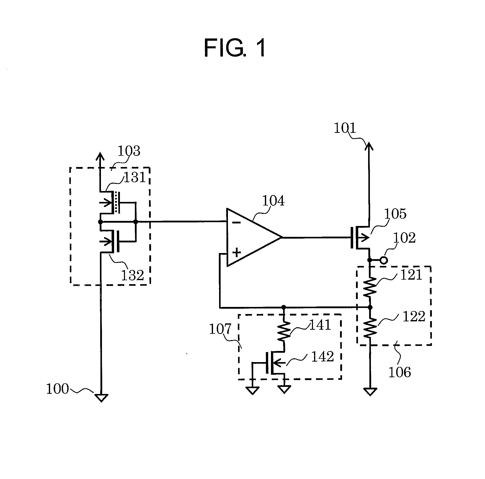
[0021]FIG. 1 is a circuit diagram illustrating a voltage regulator according to a first embodiment of the present invention. The voltage regulator of the first embodiment includes a reference voltage circuit 103, a differential amplifier circuit 104, an output transistor 105, a voltage divider circuit 106, a leakage current correction circuit 107, a ground terminal 100, a power supply terminal 101, and an output terminal 102. The voltage divider circuit 106 includes resistors 121 and 122. The leakage current correction circuit 107 includes a resistor 141 and an NMOS transistor 142. The reference voltage circuit 103 includes a depletion type NMOS transistor 131 and an NMOS transistor 132.

[0022]The connections are now described. The depletion type NMOS transistor 131 has a gate and a source both connected to a gate and a drain of the NMOS transistor 132 and an inverting input terminal of the differential amplifier circuit 104, and a drain connected to the power supply terminal 101. Th...

second embodiment

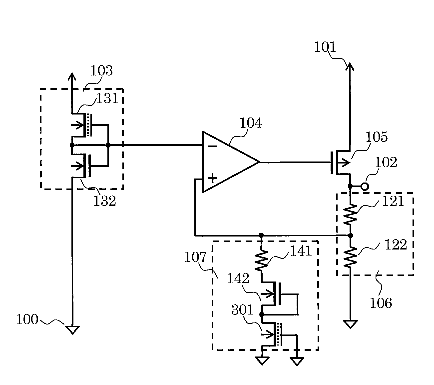
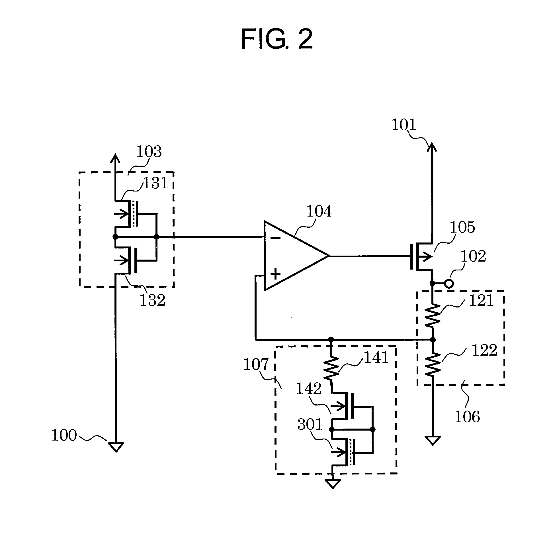
[0028]FIG. 2 is a circuit diagram illustrating a voltage regulator according to a second embodiment of the present invention. FIG. 2 differs from FIG. 1 in that the leakage current correction circuit 107 includes a depletion type NMOS transistor 301. The depletion type NMOS transistor 301 has a drain and a gate both connected to the gate and the source of the NMOS transistor 142, and a source connected to the ground terminal 100.

[0029]Next, the operations of the voltage regulator of the second embodiment are described. Because the gate and the source of the NMOS transistor 142 are connected to each other, the leakage current correction circuit 107 can cause the off leakage current to flow at high temperature, to thereby decrease the feedback voltage VFB. Due to the presence of the NMOS transistor 142, the depletion type NMOS transistor 301 does not cause a current to flow at normal temperature, but causes a junction leakage current only at high temperature. By using elements which h...

third embodiment

[0032]FIG. 3 is a circuit diagram illustrating a voltage regulator according to a third embodiment of the present invention. FIG. 3 differs from FIG. 2 in that the gate of the depletion type NMOS transistor 301 is connected to the ground terminal 100.

[0033]Next, the operations of the voltage regulator of the third embodiment are described. Because the gate and the source of the NMOS transistor 142 are connected to each other, the leakage current correction circuit 107 can cause the off leakage current to flow at high temperature, to thereby decrease the feedback voltage VFB. Due to the presence of the NMOS transistor 142, the depletion type NMOS transistor 301 does not cause a current to flow at normal temperature, but causes a junction leakage current only at high temperature. Therefore, no current flows at normal temperature even when the gate of the depletion type NMOS transistor 301 is connected to the ground terminal. The junction leakage current at high temperature is the same...


PUM


Abstract

Provided is a voltage regulator including a leakage current correction circuit capable of keeping the accuracy of an output voltage of the voltage regulator even when an output voltage of a reference voltage circuit is decreased due to the influence of a leakage current. The voltage regulator includes: a reference voltage circuit configured to output a reference voltage; an output transistor configured to output an output voltage; a voltage divider circuit configured to divide the output voltage to output a feedback voltage; an error amplifier circuit configured to amplify a difference between the reference voltage and the feedback voltage, and output the amplified difference to control a gate of the output transistor; and a leakage current correction circuit connected to an output terminal of the voltage divider circuit. The leakage current correction circuit is configured to decrease the feedback voltage to prevent the output voltage from dropping at high temperature.

Description

RELATED APPLICATIONS[0001]This application claims priority under 35 U.S.C. §119 to Japanese Patent Application No. 2013-208142 filed on Oct. 3, 2013, the entire content of which is hereby incorporated by reference.BACKGROUND OF THE INVENTION[0002]1. Field of the Invention[0003]The present invention relates to a voltage regulator configured to keep the good accuracy of an output voltage even when a reference voltage circuit is influenced by a leakage current flowing at high temperature.[0004]2. Description of the Related Art[0005]A related-art voltage regulator is now described. FIG. 7 is a circuit diagram illustrating the related-art voltage regulator.[0006]A differential amplifier circuit 104 compares a reference voltage (VREF) of a reference voltage circuit 103 and a feedback voltage (VFB) of a voltage divider circuit 106, and controls a gate voltage of an output transistor 105 so that the VREF and the VFB have the same value. When an output voltage of an output terminal 102 is re...

Claims


Application Information

Patent Timeline
IPC IPC(8): H02M3/158H02M1/08
CPCH02M3/158H02M2001/0003H02M1/08G05F1/56G05F1/468G05F1/567
Inventor KOBAYASHI, YUJISUZUKI, TERUO
Owner ABLIC INC
Why Eureka
Try Eureka