Method for manufacturing film electrode

a manufacturing method and film electrode technology, applied in the direction of electrochemical generators, cell components, coatings, etc., can solve the problems of easy degradation of electron conductivity, reduce material cost and manufacturing process complexity, and reduce catalyst loading on the catalyst support. , the effect of high open ratio

Inactive Publication Date: 2015-04-09
NATIONAL TSING HUA UNIVERSITY
View PDF7 Cites 19 Cited by
  • Summary
  • Abstract
  • Description
  • Claims
  • Application Information

AI Technical Summary

Benefits of technology

[0019]Compared to the micro-structure array manufactured by conventional techniques, the open ratio of the film electrode manufactured by the method of the present invention is estimated to be 300 to 1200 times larger (i.e. open ratio>30%), the specific surface area is 3000 times larger (3 orders of magnitude). Therefore, the method of the present invention is capable of manufacturing tightly packed and high-aspect-ratio (2:1 to 5:1) micro-hole arrays, and the method of the present invention may also reduce the material cost and the complexity of the manufacturing process. Accordingly, the catalyst loading on the catalyst support may be increased due to its high open ratio and high specific surface area, and the power density of the micro fuel cells may be further enhanced.
[0020]Recently, soft polymers are used as an electrode material in fuel cells, and the micro-structure array is directly transferred to the soft polymer substrates via casting and rolling techniques. In addition, the original silicon master mold can be used repeatedly, and the manufacturing process of the casting and rolling techniques are simpler, thus reducing the process cost.
[0021]In order to increase the configuration flexibility in portable and wearable electronic devices, the soft anode and cathode electrodes can be stacked with a proton exchange membrane to form planar or tubulate membrane electrode assembly (MEA) and become a new green power source with lower cost, lighter weight (40% lighter than conventional silicon-based fuel cells in the same volume), and smaller size for the next generation. Further, according to different ways of supplying fuel and oxidant (air or oxygen), plurality of soft MEAs can be stacked in cascade arrangement to obtain a banded micro fuel cell stack, thus achieving a target of high output voltage and high power density.

Problems solved by technology

However, the electron conductivity can easily be deteriorated due to the cracks generated by bending the gold layer.

Method used


Image

  • Method for manufacturing film electrode
  • Method for manufacturing film electrode
  • Method for manufacturing film electrode

Examples


Embodiment Construction

[0035]Preparation of a Film Electrode

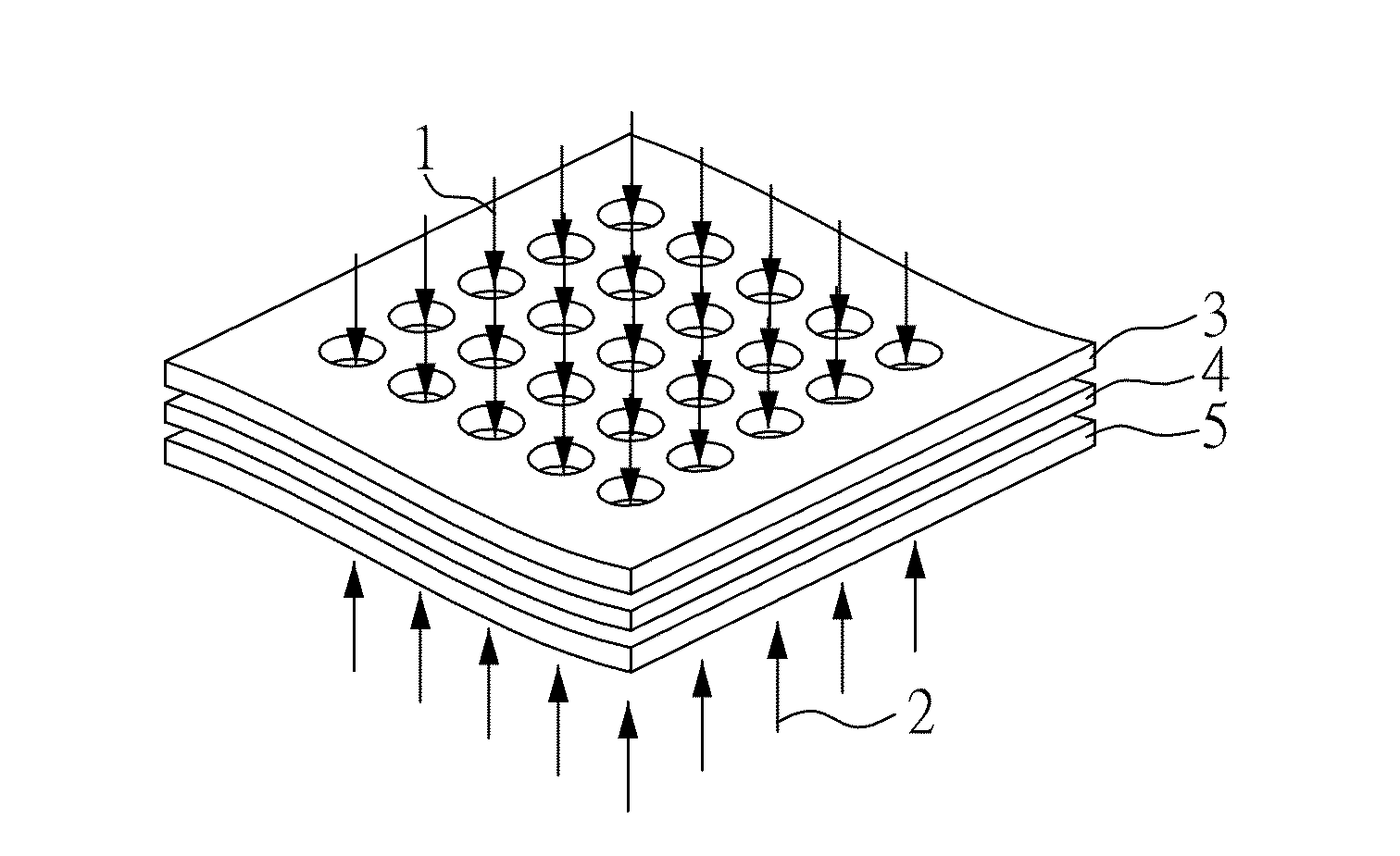
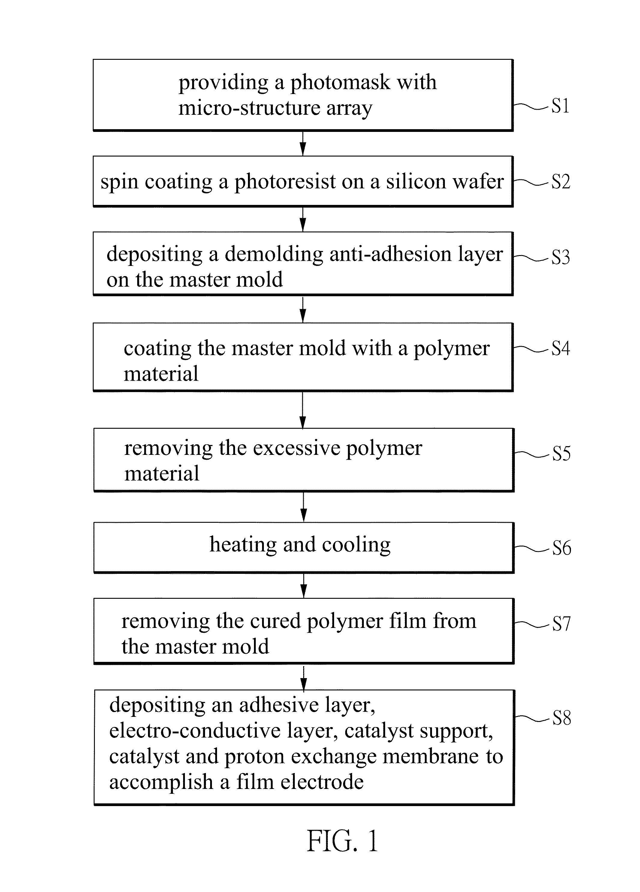
[0036]FIG. 1 shows a preferred embodiment of the method for manufacturing a film electrode of the present invention. With reference to FIG. 1, steps S1 to S8 of the manufacturing process will be described in detail as follows. Step S1: providing a photomask with micro-structure array; step S2: spin coating a SU-8 photoresist on a silicon wafer (spin coating speed: 1300˜2000 rpm), performing a lithography process with the photomask (soft baking: heating from 35° C. to 95° C. by 5° C. every step, holding the temperature for 3 minutes, holding the temperature for 30 minutes at 65° C. and 95° C.; post-exposure baking: holding the temperature for 5 minutes at 65° C., and holding the temperature for 1 minute at 95° C.), and removing the unexposed area to form a master mold with plurality of micro pillars, wherein the diameter of the plurality of micro pillars is ranging from 20 to 80 μm, the height is ranging from 50 to 250 μm, and the aspect ratio is ...


PUM

PropertyMeasurementUnit
thicknessaaaaaaaaaa
diameteraaaaaaaaaa
diameteraaaaaaaaaa

Abstract

A method for manufacturing a film electrode is disclosed, which comprises the following steps: (A) providing a polymer substrate, and forming a micro-structure array comprising a plurality of micro holes on the polymer substrate; and (B) depositing sequentially an electron-conductive layer, a catalyst layer, and a proton exchange membrane on the array comprising a plurality of micro holes to form a film electrode; wherein the aspect ratio of the plurality of micro holes is ranging from 2:1 to 5:1.

Description

CROSS REFERENCE TO RELATED APPLICATION[0001]This application claims the benefits of the Taiwan Patent Application Serial Number 102136466, filed on Oct. 9, 2013, the subject matter of which is incorporated herein by reference.BACKGROUND OF THE INVENTION[0002]1. Field of the Invention[0003]The present invention relates to a method for manufacturing a film electrode, more particularly, to a method for manufacturing a film electrode with low cost and high production yield.[0004]2. Description of Related Art[0005]Basic necessities of human life are closely related to energy, and the major source of energy relies on oil. However, oil is not inexhaustible or always available for use. According to the history, three outbreaks of oil crisis caused the inflation of price; therefore, the development for green energy becomes the primary target among nations. It is well known that fuel cells have the features of high energy density, high energy conversion efficiency and environmental friendly (...

Claims


Application Information

Patent Timeline
Patent Type & Authority Applications(United States)
IPC IPC(8): H01M4/88
CPCH01M4/8875H01M4/8825H01M2250/30H01M4/8817H01M4/8892H01M4/8803H01M4/926H01M2008/1095Y02E60/50
Inventor TSENG, FAN-GANGWU, YI-SHIUANLU, CHIA-LIENLIN, LIANG-YOU
Owner NATIONAL TSING HUA UNIVERSITY
Why Eureka
Try Eureka