Rocket launch tower

a rocket launch tower and rocket technology, applied in the field of rocket launch towers, can solve the problems of high cost, inability to deliver even a small payload to space, and inefficient rocket launch, so as to improve the reliability of rockets, increase the payload capacity of existing rockets, and save resources

Inactive Publication Date: 2015-04-16
ESSBAUM ALEXANDER DANKWART
View PDF14 Cites 16 Cited by
  • Summary
  • Abstract
  • Description
  • Claims
  • Application Information

AI Technical Summary

Benefits of technology

[0049]An advantage of the invention is that it provides a relatively inexpensive, reusable, and reliable way to increase the payload capacity of existing rockets.
[0050]A further advantage of the invention is that it provides a mechanism to reproduce the acceleration of a flying rocket in a non-destructive and repeatable fashion. The invention can simply subject a test article to the appropriate acceleration and then brake to a stop before the test article exits the top of the structure. The platform can then be lowered back to the ground and the test article inspected. This feature of the invention will improve rocket reliability through component testing and should allow rocket designers to produce more efficient rockets by removing the tendency to over-design a component that cannot otherwise be sufficiently tested. Rocket designers are currently limited in their ability to test large rocket components. The only way to subject the structure and components of a rocket to the loads imparted on it by launch and ascent is to launch the rocket. This is failure-prone (any major failure during flight results in destruction of the rocket) and rarely involves the ability to inspect the components after flight (most rockets, and certain components of all rockets) are non-recoverable (lost in space, destroyed in re-entry, damaged or destroyed on impact with the sea or the ground, etc.) This feature of the invention will improve rocket reliability through component testing and should allow rocket designers to produce more efficient rockets by removing the tendency to over-design a component that cannot otherwise be sufficiently tested.

Problems solved by technology

Launching rockets into space is very energy intensive and inefficient.
This makes it extremely costly to deliver even a small payload to space (going rates are $5000-$10,000 per kilogram).
A number of inventions have been proposed to provide ground-based power for helping to launch rockets but so far none have been implemented successfully.
Using this solution, the greatest acceleration a falling object can achieve is 1 g. A counterweight using a simple fixed pulley that is lifting a load will always accelerate at less than 1 g. Therefore, a simple pulley lifting a rocket launch platform will accelerate a rocket at less that 1 g. As a traditional rocket already accelerates upward at around 0.5 g such a counterweight launch arrangement does not provide much benefit, or requires an extremely tall tower structure.
Containing recirculated exhaust gas requires either a chamber sealed to the engines of the rocket (which is technically complicated and prone to damage the engines due to backpressure) or an unsealed or partially sealed chamber that would provide inconsistent pressure and therefore inconsistent acceleration of the rocket.
Electric motors to propel a rocket would be excessively large and require an excessive amount of energy at launch—this is technically difficult and expensive to achieve.
Such a large sealed chamber (like a giant gun barrel) is impractical and excessively expensive to manufacture for the size necessary, and the machinery necessary to smoothly but powerfully fill this giant cylindrical barrel would be excessively large, complex, and expensive.
No such material exists that will contain sufficient energy over a sufficient range of motion to make an elastic launch system useful or practical.
Moreover, none of the existing rocket launch mechanisms provide the capacity to finely adjust and control the upward acceleration in the range appropriate and useful for a rocket.
Too much acceleration (over about 5 g) will damage the rocket, and too little will not provide enough assistance to guarantee the rocket reaches orbit with its additional payload.
Additionally, none of the existing rocket launch mechanisms guarantee that the rocket will be accelerated in a straight line, with no tilting or lateral movement (movement perpendicular to the centerline of the rocket).
Rockets are relatively fragile in all directions excepting a steady push from below, and any system that does not provide for a smooth enough, straight vertical acceleration is prone to damage the rocket.
Finally, prior attempts failed to take into account the limited acceleration provided by a simple (non-multiplying) pulley arrangement, as well as the need to precisely control the acceleration as well as lateral and tilting movement of the launch platform.
In the absence of these features, a gravity-powered launch tower would not be useful.

Method used


Image

  • Rocket launch tower
  • Rocket launch tower
  • Rocket launch tower

Examples


Embodiment Construction

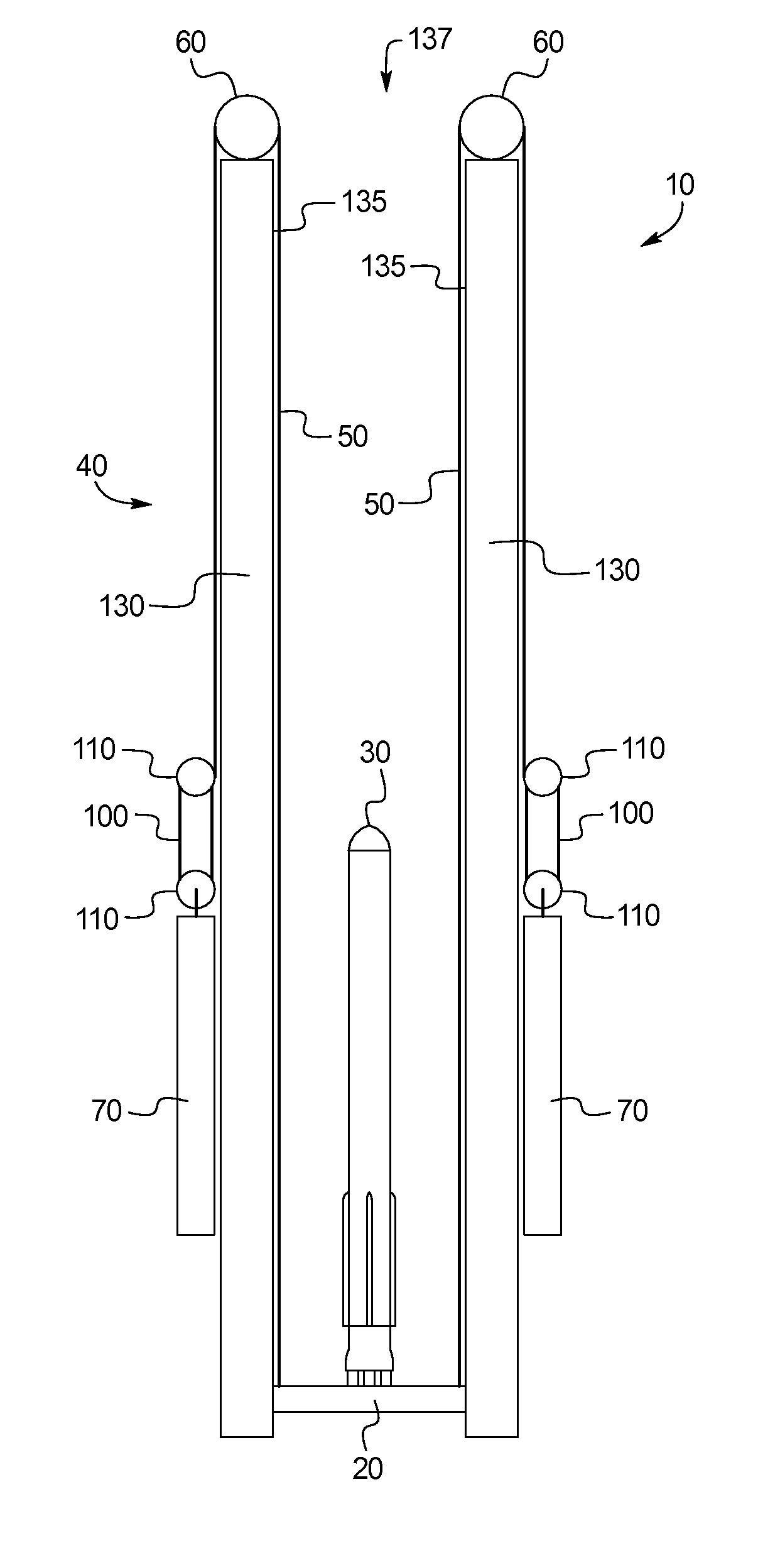
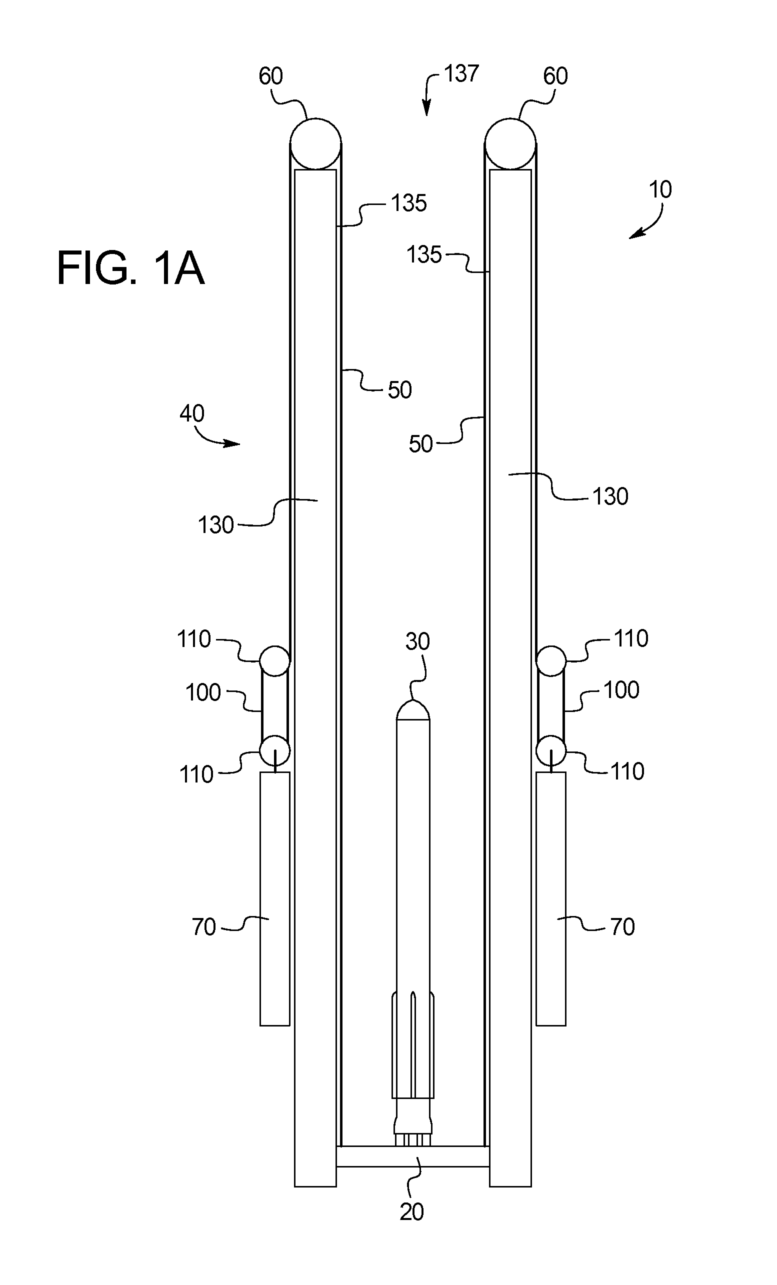
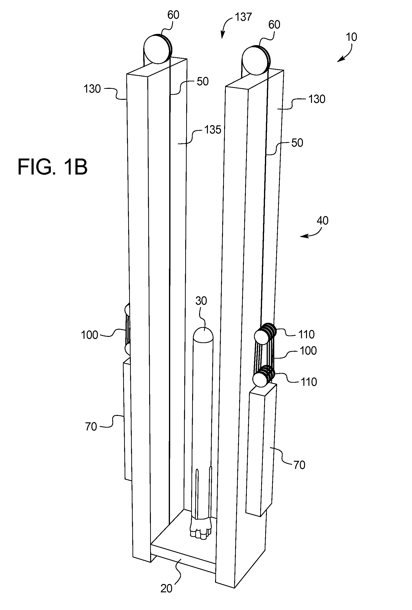
[0065]FIGS. 1a and 1b illustrates an embodiment of a rocket launch tower 10. The rocket launch tower 10 includes a platform 20 that supports a rocket 30. In use, the rocket launch tower 10 launches the rocket 30 from the upward-moving platform 20 thereby imparting energy into the rocket 30 before or in conjunction with the rocket 30 using its own propellant.

[0066]The platform 20 may be connected to cables 50 to provide the upward force during launch. The cables 50 may, in turn, connect the platform 20 to an arrangement of counterweights 70 via a pulley system. During launch, the counterweights 70 are allowed to fall, accelerating the cables 50 to cause upward movement of the platform 20. A surrounding structure 40 guides the platform 50 and provides support to the cables 50 via pulleys 60 at the top of surrounding structure 40 that engage the cables 50. As shown, the surrounding structure 40 may include one or more guide towers 130 that may guide the platform 20 during ascent.

[0067]...


PUM


Abstract

A rocket launch tower is provided, including: a vertical support structure including two or more guide towers defining a vertical shaft between the two or more guide towers, each guide tower including one or more pulleys engaging one or more cables; a platform located within the vertical shaft and connected to the one or more cables; a drive mechanism that applies a force to the one or more cables to accelerate the platform along a trajectory within the vertical shaft; one or more sensors collecting data regarding the position of the platform along the trajectory within the vertical shaft and communicating the platform position data to a controller, the controller in communication with an acceleration control system including one or more brakes acting on the platform; wherein the controller causes the acceleration control system to actively correct the platform acceleration towards an intended platform acceleration.

Description

CROSS-REFERENCE TO RELATED APPLICATIONS[0001]This application claims priority to and the benefit of U.S. Provisional Application 61 / 858,549, filed Jul. 25, 2013 and to U.S. Provisional Application 61 / 869,322, filed Aug. 23, 2013 both of which are hereby incorporated by reference.BACKGROUND OF THE INVENTION[0002]The present subject matter relates generally to a rocket launch tower having pre-acceleration of the rocket before powered flight. More specifically, the present invention relates to a rocket launch tower that uses falling counterweights to accelerate and stabilize a platform supporting a rocket at a higher rate of speed than the speed of the counterweights.[0003]Launching rockets into space is very energy intensive and inefficient. Modern launch vehicles are able to deliver between 1% (Space Shuttle) and at most 4% (Saturn V) of the total vehicle mass at launch into low earth orbit. This makes it extremely costly to deliver even a small payload to space (going rates are $500...

Claims


Application Information

Patent Timeline
Patent Type & Authority Applications(United States)
IPC IPC(8): F41F3/073F41F3/04B64F1/06
CPCF41F3/073B64F1/06F41F3/04F41F7/00B64G5/00
Inventor ESSBAUM, ALEXANDER DANKWART
Owner ESSBAUM ALEXANDER DANKWART
Why Eureka
Try Eureka