Sub-surface formation boundary detection using an electric-field borehole telemetry apparatus

a technology of electric field boreholes and telemetry devices, which is applied in the direction of survey, directional drilling, borehole/well accessories, etc., can solve the problems of increasing the cost of drilling, the inclination of the borehole may vary a lot, etc., and achieves the control of the borehole trajectory, facilitate the subsequent fracking and fracking locating procedure, and reduce the cost

Inactive Publication Date: 2015-04-16
SCIENCE DRILLING INTERNATIONAL INC
View PDF5 Cites 10 Cited by
  • Summary
  • Abstract
  • Description
  • Claims
  • Application Information

AI Technical Summary

Benefits of technology

[0007]It is a major objective of this invention to provide an improved method to detect a sub-surface formation boundary or boundaries, using an electric field borehole telemetry apparatus. This is useful for example to facilitate subsequent fracking and fracking locating procedure in shale. This method enables use of the telemetry apparatus to transmit inclination, direction and logging parameters to the surface for use in steering the drill string to remain in the formation, i.e. relative to the formation boundary, and particularly both up and down boundaries, in a way that substantially benefits results in terms of better control of the borehole trajectory at a lower cost. The invention also provides a method for assisting in steering a drill bit so as to maintain the drill bit in a sub-surface bed or seam, during drilling, enabling the borehole to be used for reception of fracking equipment. The method of the invention includes detecting the relative position of the drill bit with respect to a formation boundary or boundaries, using an electric-field borehole telemetry apparatus.

Problems solved by technology

Given this limitation, such boreholes may have considerable variation in inclination as the path of the drill bit is steered.
Further, conventional resistivity tools would increase the length of the bottom hole assembly at the bottom of the drill string and would increase the cost of drilling.

Method used


Image

  • Sub-surface formation boundary detection using an electric-field borehole telemetry apparatus
  • Sub-surface formation boundary detection using an electric-field borehole telemetry apparatus
  • Sub-surface formation boundary detection using an electric-field borehole telemetry apparatus

Examples


Embodiment Construction

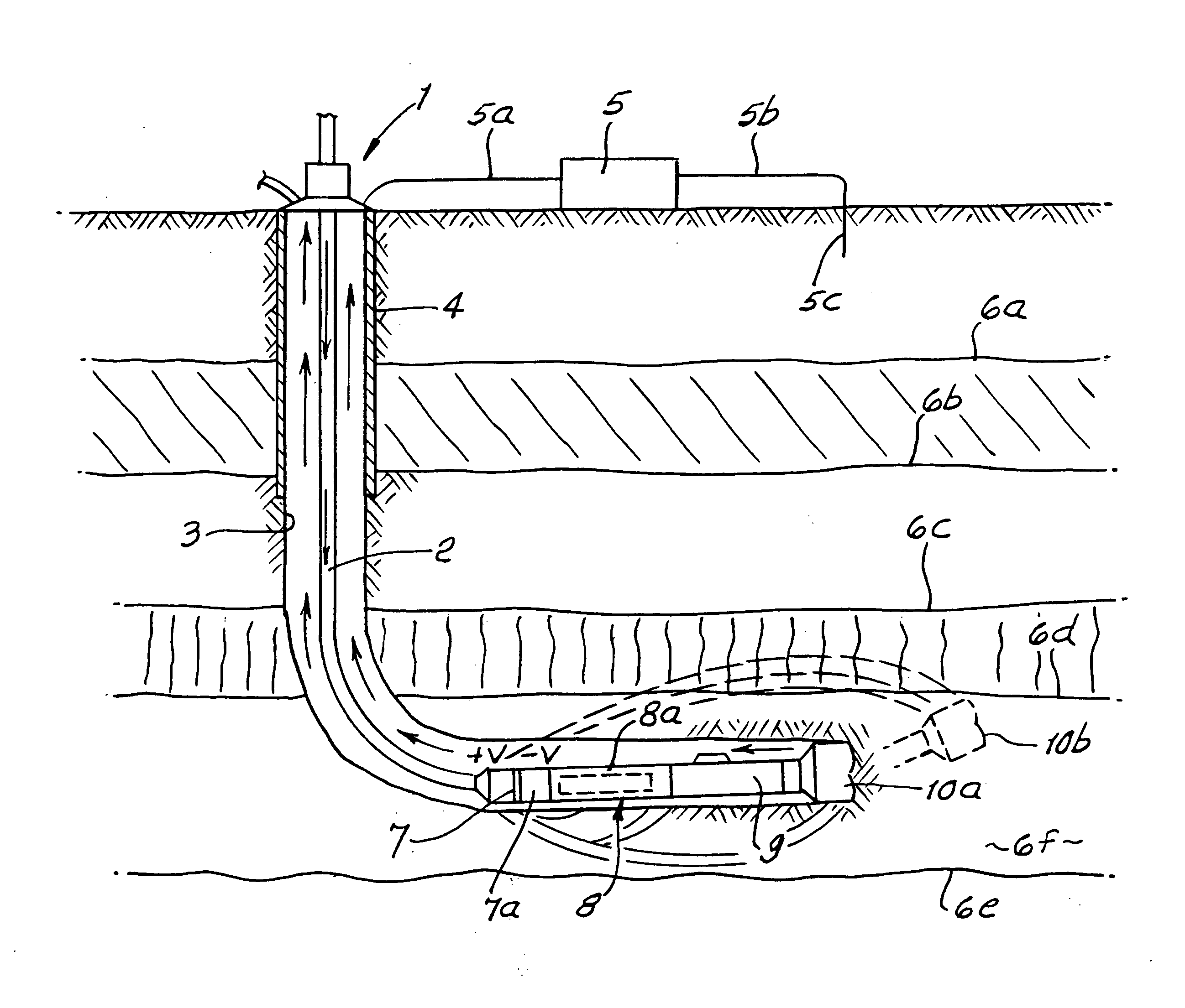
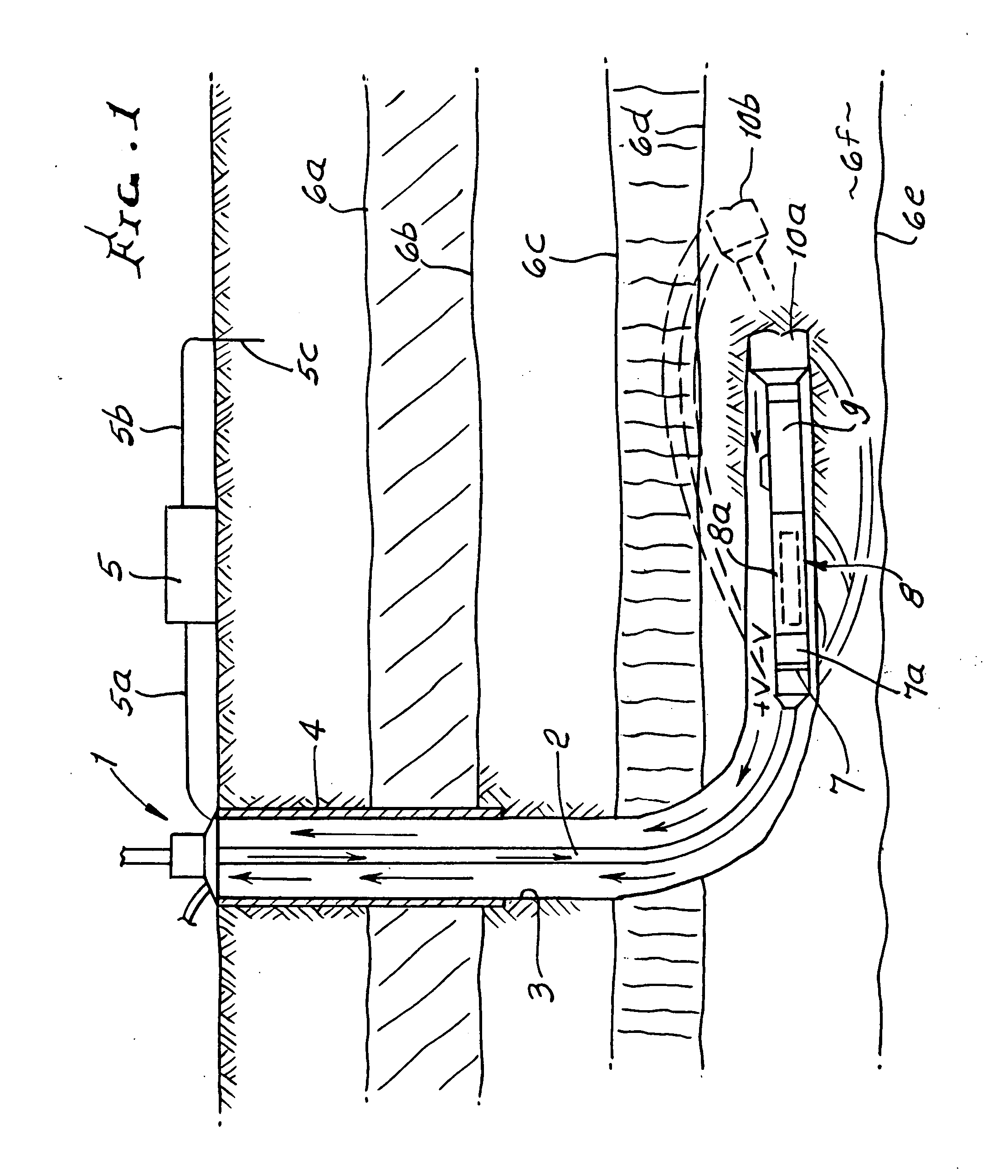
[0043]FIG. 1 shows a typical drilling process including a drill string, an insulating gap in the string near the bit, and various layers of underground material in the region of a selected seam or formation layer. A drill rig 1 at the surface of the earth is connected to a drill string 2 penetrating down into the earth. The upper portion of the borehole is shown with casing 4, and the open hole 3 continues below the casing. An insulating gap 7 in the string is at or proximate the lower end of the drill string. Below the insulating gap a non-magnetic collar 8 in the string contains a measure-while-drilling (MWD) apparatus indicated at 8a. A mud motor 9, below 8, is or may be used to rotatably operate a rotary drill bit 10a. A future projection of the location of the drill bit indicated at 10b shows where the drill bit is projected to be at some future time. At the surface, an electronics assembly 5 is shown electrically connected to the upper end of the drill string, as by connection...


PUM


Abstract

The method of maintaining drill bit advancement in an underground formation that contains shale, including providing an electrical signal from an insulated gap location in a drill string substantially directly behind the bit in the formation, detecting substantial change in a signal as the bit advances, and changing the direction of drilling of the bit as a function of a signal change, to thereby maintain the direction of bit advancement in the formation.A method is disclosed for detecting the existence and direction of adjacent bed boundaries. A short hop transmitter assembly generates a signal that is detected by an associated receiver assembly. The received signal(s) are tied to the azimuthal orientation of the transmitter or receiver and processed to yield the direction and / or the distance of the bed boundary. This information is transmitted to the surface via surface telemetry for real-time control of the drilling assembly to stay within, or to enter, a pay zone.

Description

[0001]This application is a continuation-in-part of pending U.S. Ser. No. 11 / 584,778, filed Oct. 23, 2006.BACKGROUND OF THE INVENTION[0002]This invention relates generally to sub-surface formation boundary detection and more specifically to method and apparatus for such detection using borehole telemetry apparatus.[0003]It is known that shale in natural formations may contain significant amounts of hydrocarbon. It is further well known that significant amounts of hydrocarbon can be recovered by boring holes into the formation and using so-called fracking techniques. Such beds may extend generally horizontally, and be relatively thin in vertical extent. U.S. Pat. Nos. 6,280,000 and 6,425,448 describe examples of such drilling and show particular patterns of holes to drain methane from a coal formation. In the boring of such holes, method and means are needed to steer the drilling progress, so as to remain in the bed and, to the extent possible, bore a straight hole such that up and d...

Claims


Application Information

Patent Timeline
Patent Type & Authority Applications(United States)
IPC IPC(8): E21B47/12E21B43/12E21B43/00E21B43/26E21B7/04E21B7/28
CPCE21B47/121E21B7/04E21B7/28E21B43/006E21B43/26E21B43/12E21B7/046E21B7/068E21B7/10E21B47/125E21B47/026E21B47/12E21B47/02E21B47/13E21B47/0228E21B47/0232
Inventor WHITE, MATTHEW A.SUH, ASONG E.GRAF, STEPHAN
Owner SCIENCE DRILLING INTERNATIONAL INC
Why Eureka
Try Eureka