Renewable energy site reactive power control

a reactive power and renewable energy technology, applied in the direction of active power filtering, parallel operation of dc sources, transportation and packaging, etc., can solve the problems of reducing controller stability, minimal benefit, and reactive power and voltage commands subject to site voltage and power factor operating limits, so as to reduce the detrimental effect of loop delay

Active Publication Date: 2015-04-16
TMEIC
View PDF4 Cites 29 Cited by
  • Summary
  • Abstract
  • Description
  • Claims
  • Application Information

AI Technical Summary

Benefits of technology

[0013]To this end, the present invention provides an improved method, computer program product, controller device, and system for reactive power control at a renewable energy site. The present invention addresses dynamic performance problems associated with significant control loop delay and the changing modes of operation required to meet utility voltage and reactive power constraints. Key elements include a reactive power control term based on the sum of a single integrator and feed-forward compensation term, an integrator anti-windup mechanism based on the status of individual inverters, a means for decreasing detrimental effects of loop delay during reactive power reference changes, and a means of implementing voltage and power factor limits with smooth transfer between reactive power operating regions.

Problems solved by technology

Furthermore, reactive power and voltage commands are subject to site voltage and power factor operating limits.
In reactive power control mode, the two series PI controllers can contribute excessive phase lag when the P gain is low, which decreases controller stability.
However there is minimal benefit in this case, since voltage and reactive power are mutually dependent).
3. There is no means to apply reactive power threshold control during voltage control.

Method used


Image

  • Renewable energy site reactive power control
  • Renewable energy site reactive power control
  • Renewable energy site reactive power control

Examples


Embodiment Construction

[0041]Reference will now be made in detail to various exemplary embodiments of the invention. It is to be understood that the following discussion of exemplary embodiments is not intended as a limitation on the invention. Rather, the following discussion is provided to give the reader a more detailed understanding of certain aspects and features of the invention.

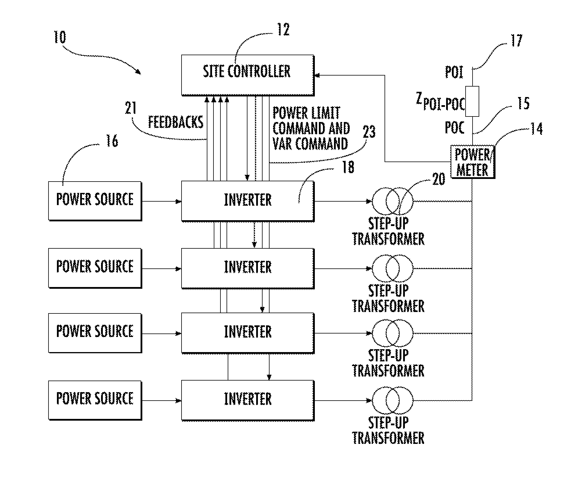
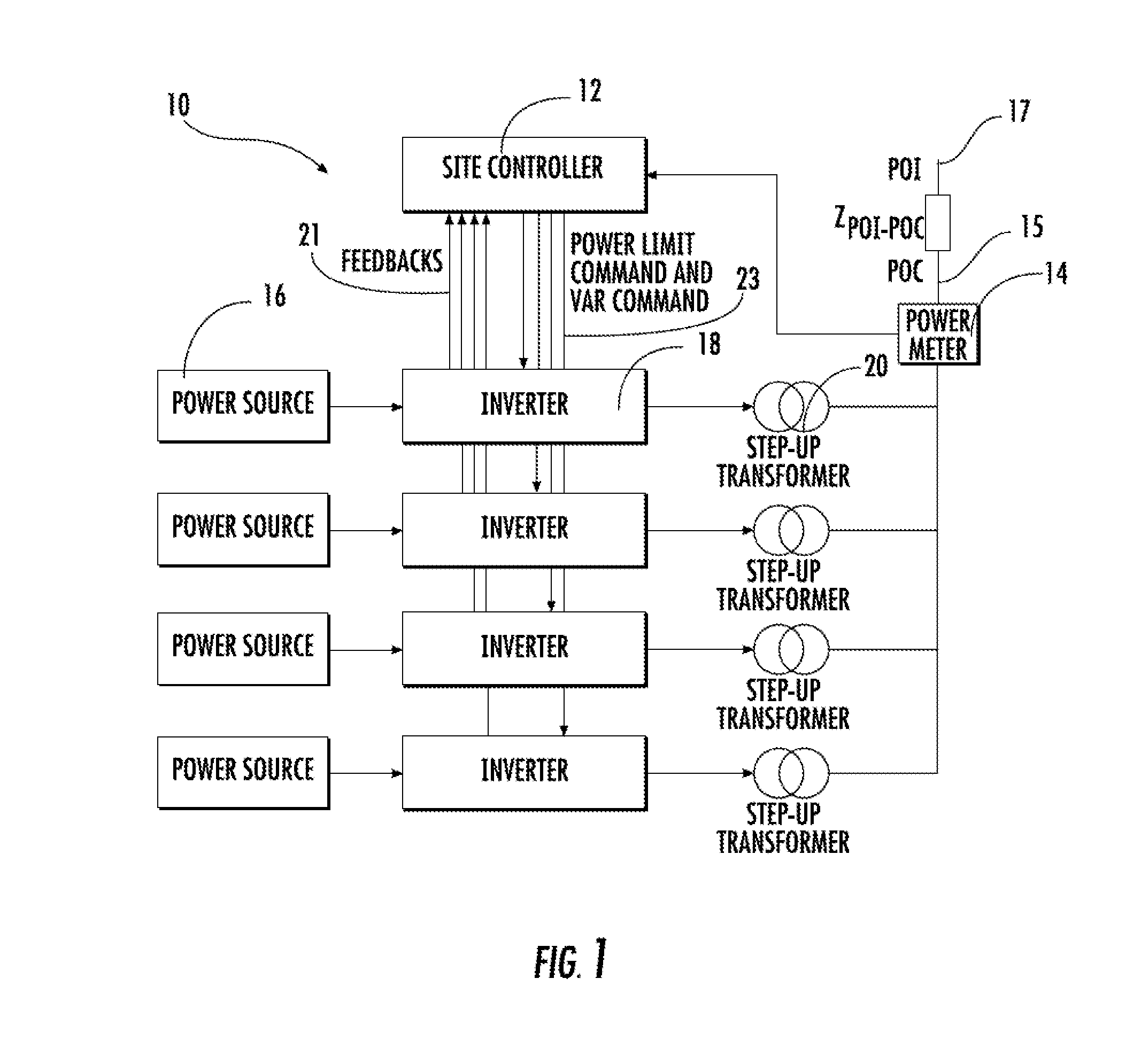
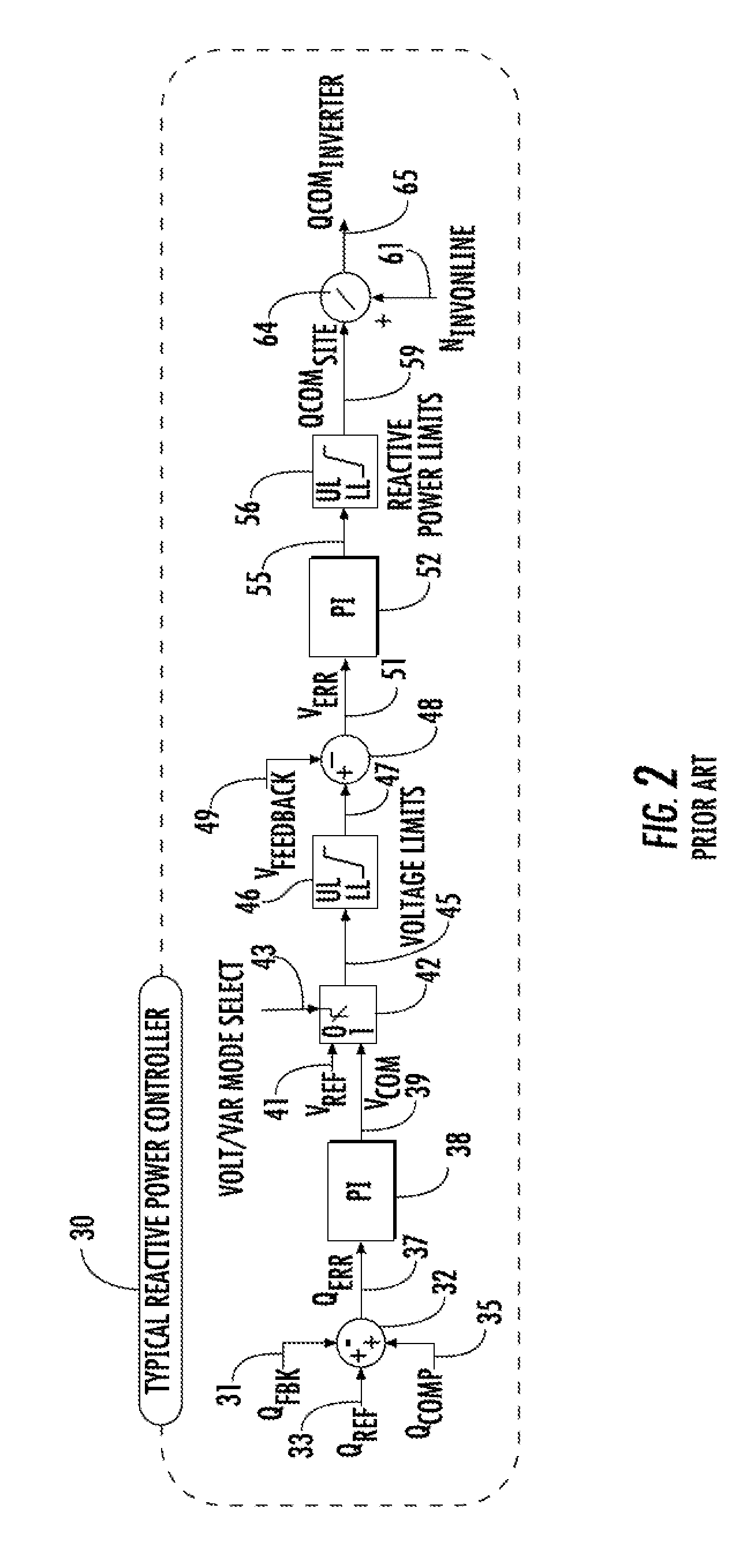
[0042]Embodiments of the present invention provide improved regulation of reactive power at a renewable energy plant that entails two modes of operation:

[0043]1. Power factor control—a closed loop regulator which controls site power factor without exceeding site voltage thresholds

[0044]2. Voltage control—a closed loop regulator which controls site voltage without exceeding site power factor thresholds.

[0045]Thus, embodiments of the invention provide for threshold control wherein reactive power limits are imposed during voltage control and voltage limits are imposed during reactive power control.

[0046]Further, in certain embo...


PUM


Abstract

Methods, systems, controller devices, and computer program products for reactive power control at a renewable energy site are provided. Embodiments address dynamic performance problems associated with control loop delay and the changing modes of operation for meeting utility voltage and reactive power constraints. Provided is a method for reactive power control involving: (a) determining a site-wide reactive power command comprised by a sum of a reactive power feedforward or compensation term and an integrator term; and (b) distributing the site-wide reactive power command among inverters. Embodiments can include a reactive power control term based on the sum of a single integrator and feed-forward compensation term, an integrator anti-windup mechanism based on the status of individual inverters, a means for decreasing detrimental effects of loop delay during reactive power reference changes, and/or a means of implementing voltage and power factor limits with smooth transfer between reactive power operating regions.

Description

BACKGROUND OF THE INVENTION[0001]1. Field of the Invention[0002]The present invention relates to control of reactive power at a renewable energy site. More particularly, the present invention relates to improvements on traditional renewable energy site reactive power and voltage control systems subject to utility voltage and reactive power limits and significant control loop delay.[0003]2. Description of Related Art[0004]Renewable energy sites are typically composed of multiple power conversion devices connected in parallel generating fixed frequency AC power to a grid. The devices are typically AC-AC or DC-AC inverters. Inverters are designed to extract maximum power from the renewable power supply, subject to a real power limit reference and often, a reactive power or voltage command.[0005]A typical reactive power control system measures site total power feedback, reactive power and site voltage to actively control them. The site control loop consists of commands from the controll...

Claims


Application Information

Patent Timeline
Patent Type & Authority Applications(United States)
IPC IPC(8): H02J3/18H02M1/42
CPCH02J3/18H02M1/4208H02M1/4233H02J3/16H02J3/1842H02J3/381H02J3/50H02J3/46Y02B70/10Y02E40/20Y02E40/30
Inventor RUDOLPH, BENJAMIN D.BIXEL, PAUL S.
Owner TMEIC
Why Eureka
Try Eureka