Two-shaft hinge antenna and foldable electronic device using the same
a technology of hinge antenna and electronic device, which is applied in the direction of antennas, antenna details, electrical devices, etc., can solve the problems of affecting the reception of antenna signals, reducing the effective transmission distance and signal quality, and reducing the yield of antennas, so as to achieve the effect of shortening the manufacturing process and improving yield
- Summary
- Abstract
- Description
- Claims
- Application Information
AI Technical Summary
Benefits of technology
Problems solved by technology
Method used
Image

Examples
first embodiment
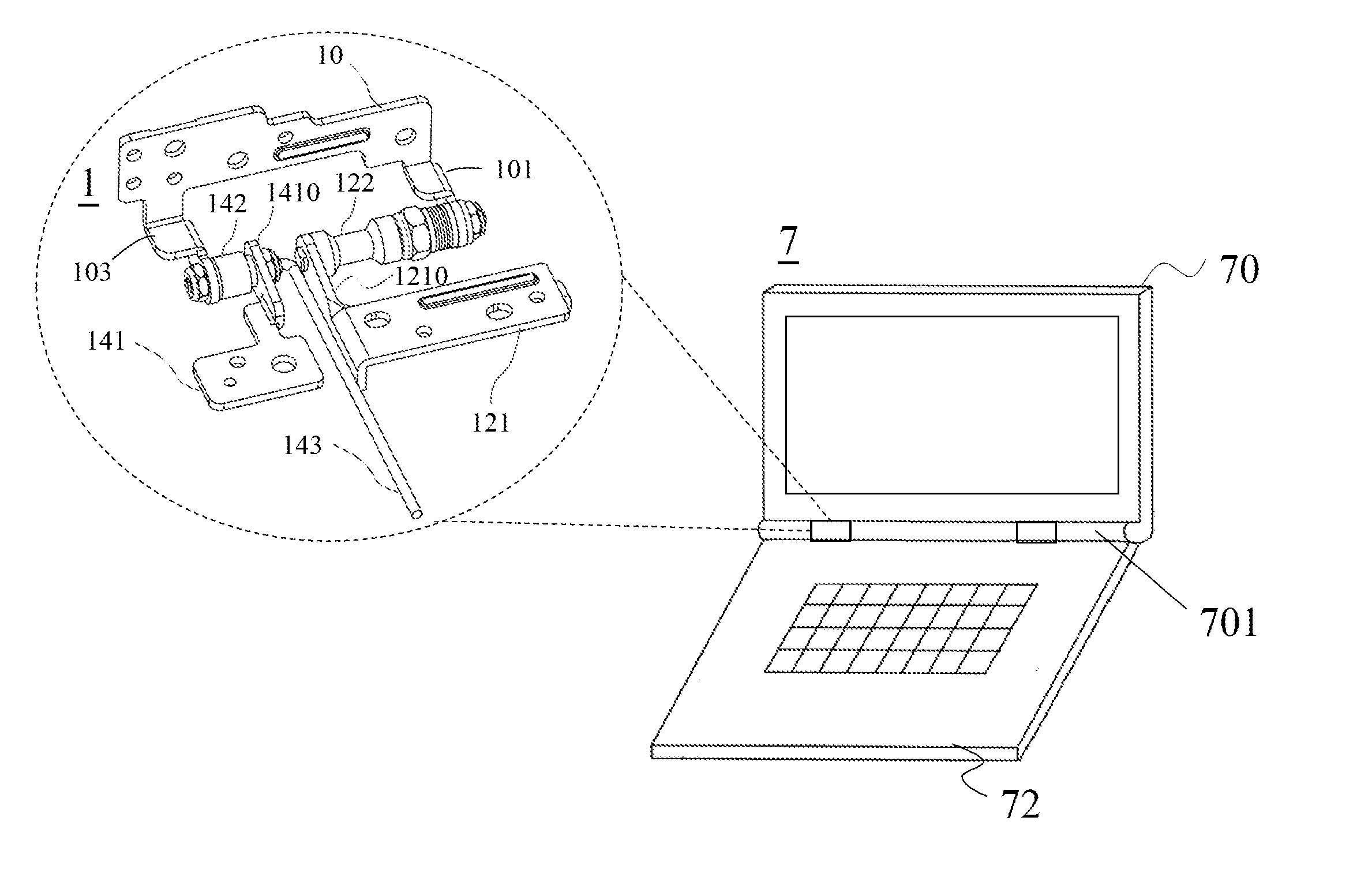
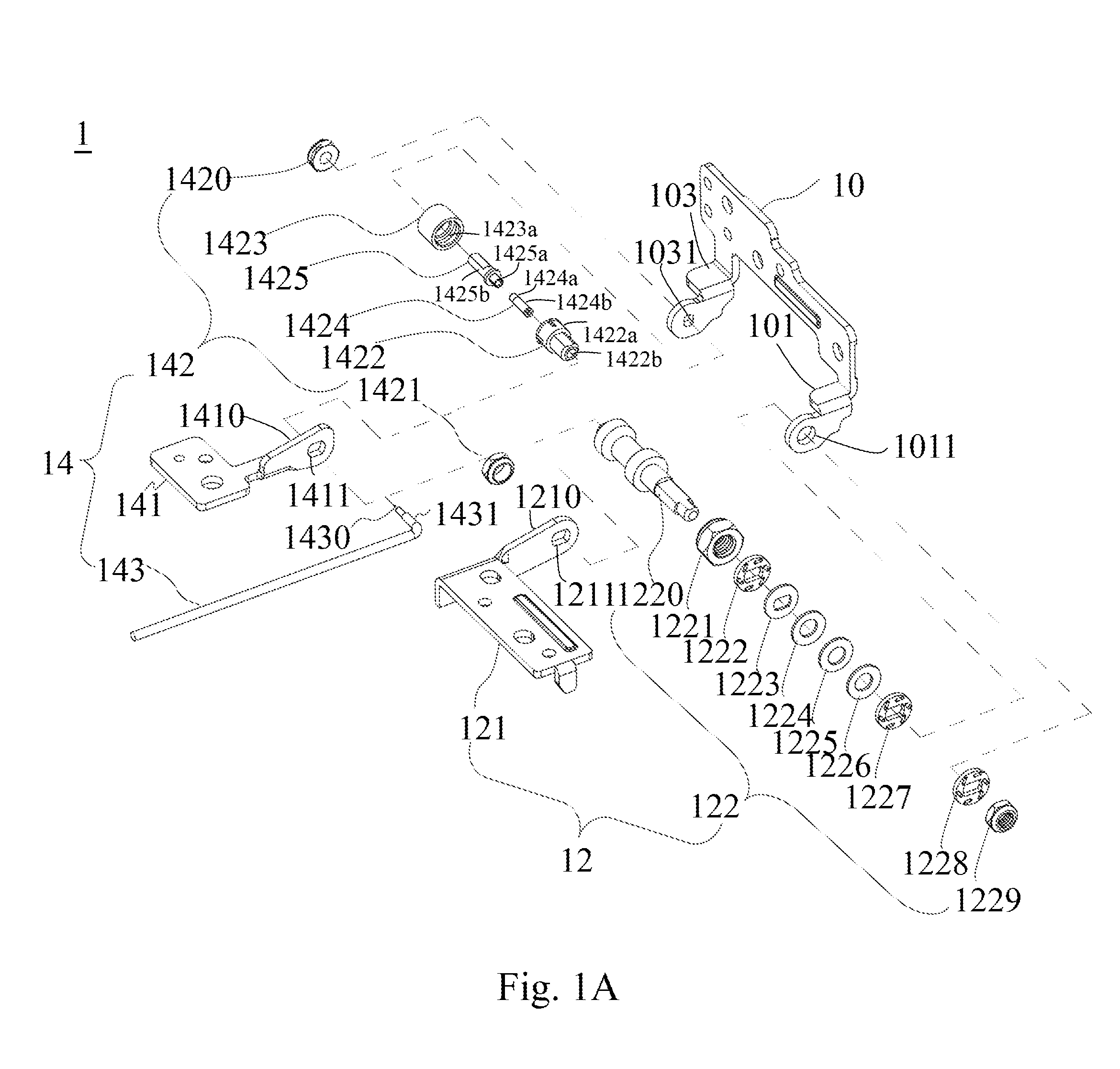
[0034]First refer to FIG. 1A, which is an explosive view of a two-shaft hinge antenna according to the present invention. As shown in FIG. 1A, the two-shaft hinge antenna 1 comprises a major conductor 10, a first rotating element 12 and a second rotating element 14, wherein both sides of the major conductor 10 are provided with opposing stretching arms 101 and 103, respectively, the ends of the stretching arms 101 and 103 are provided with a first insertion hole 1011 and a second insertion hole 1031, respectively. The first insertion hole 1011 is configured for the assembling and holding of the first rotating element 12. The first rotating element 12 further includes a first vice conductor 121, of which a stretching arm 1210 is provided with a first fitting hole 1211; and a torque device 122 having a rotation shaft 1220 and a plurality of fastening elements 1221-1229, wherein one end of the rotation shaft 1220 penetrates the plurality of fastening elements 1221-1229, and is assemble...
second embodiment
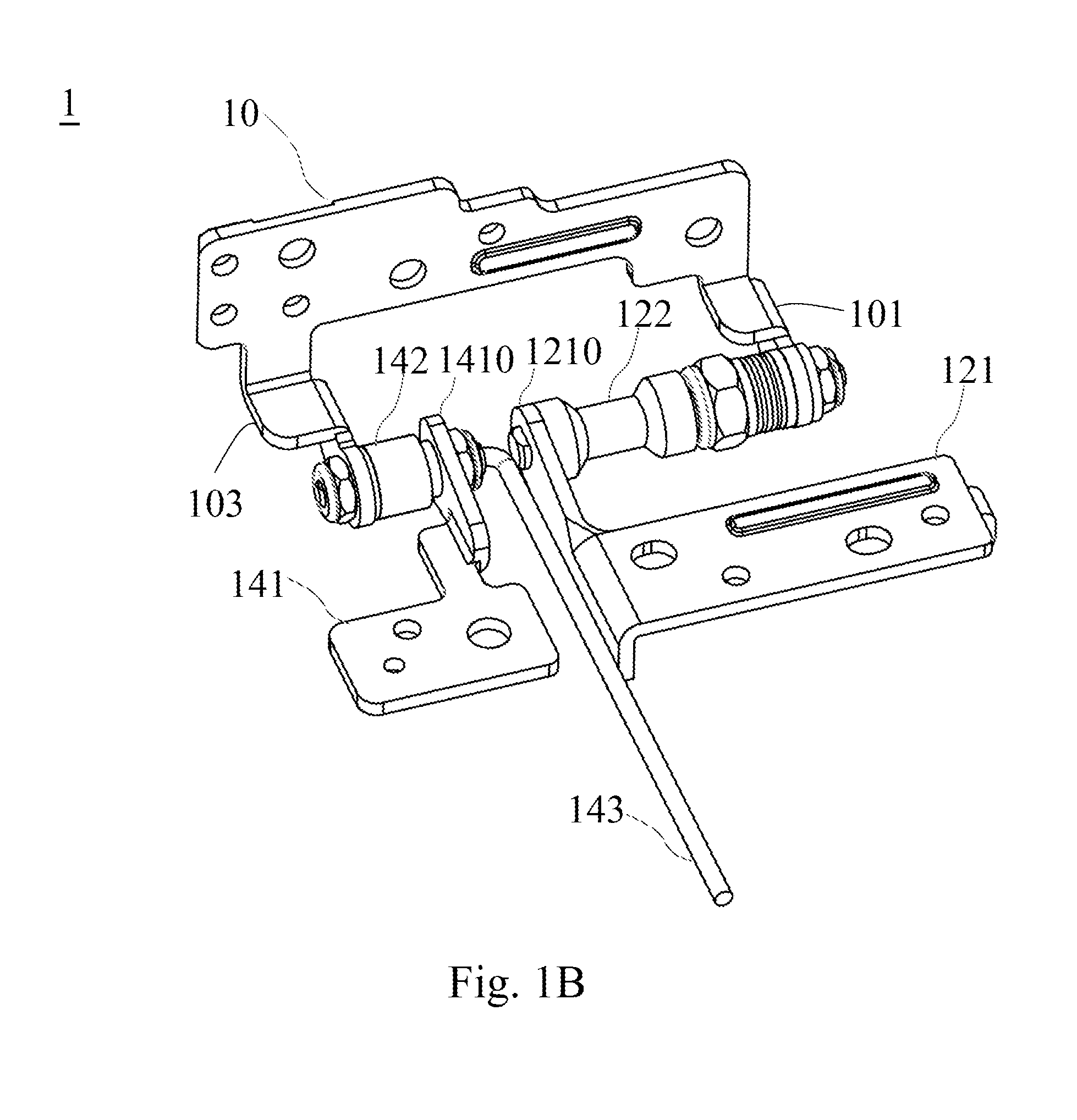
[0042]Next, please refer to FIG. 3B, which is an assembled schematic view of the two-shaft hinge antenna according to the present invention. From FIG. 3B, the assembled structure of the aforementioned FIG. 1A can be clearly seen. The first insertion hole, which is provided on the end of the stretching arm 101 on a side of the major conductor 10, is configured to be penetrated by the torque device 122 that is then fastened to the major conductor 10 by the fastening elements. The stretching arm 1210 on a side of the first vice conductor 121 is mounted to the other end of the torque device 122. After finishing the assembling of the abovementioned components, the structure of the first rotating element is constructed. The second insertion hole 1031, which is provided on the end of the stretching arm 103 on the other side of the major conductor 10, is configured to be penetrated by the rotating member 1602 of the connection device 160 which is then fastened to the major conductor 10 by t...
third embodiment
[0047]Next, please refer to FIG. 5A, which is an explosive view of the two-shaft hinge antenna according to the present invention. The structure shown in FIG. 5A is obviously similar to those of FIG. 3A or 4A and thus will not be described in detail. The structure shown in FIG. 5A differs from those of FIG. 3A or 4A in that the second insertion hole 1031, which is provided on the end of the stretching arm 103 on one side of the major conductor 10, is configured for the mounting of a second rotating element 20. The second rotating element 20 further comprises a signal feeding line 2010 configured for transmitting a high frequency signal and having a positive end signal lead 2010a and a negative end signal lead 2010b; and a microwave base plate 201 having a signal feed-in section 2011 and a grounding section 2012, wherein the signal feed-in section 2011 includes a signal pad 2011a which can be electrically connected to the positive end signal lead 2010a of the signal feeding line 2010...
PUM
 Abstract
Description
Claims
Application Information
 - R&D
- Intellectual Property
- Life Sciences
- Materials
- Tech Scout
- Unparalleled Data Quality
- Higher Quality Content
- 60% Fewer Hallucinations
Browse by: Latest US Patents, China's latest patents, Technical Efficacy Thesaurus, Application Domain, Technology Topic, Popular Technical Reports.
© 2025 PatSnap. All rights reserved.Legal|Privacy policy|Modern Slavery Act Transparency Statement|Sitemap|About US| Contact US: help@patsnap.com