

Method and apparatus for high-performance compact volumetric antenna with pattern control
a volumetric antenna, pattern control technology, applied in the field of antennas, can solve the problems of inefficient radiating of helical antennas, inapplicability, and inability to achieve the effect of maximizing magnetic field, wide bandwidth, and increasing the intrinsic inductive reactance of antennas
- Summary
- Abstract
- Description
- Claims
- Application Information
AI Technical Summary
Benefits of technology
Problems solved by technology
Method used
Image

Examples
Embodiment Construction
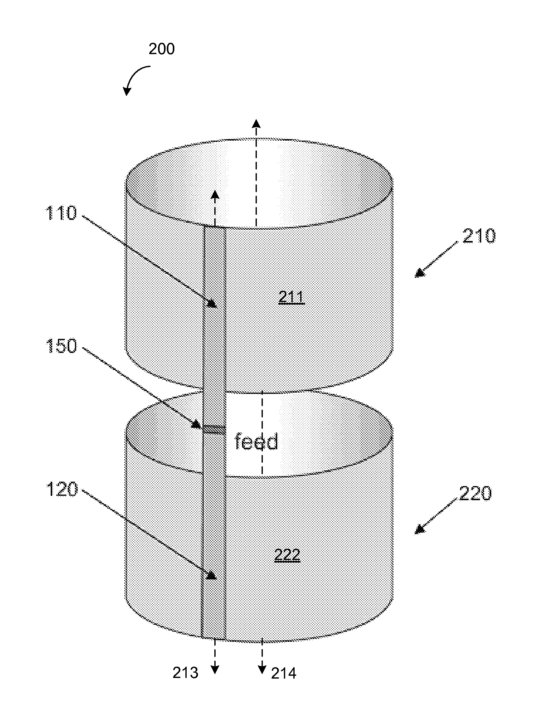
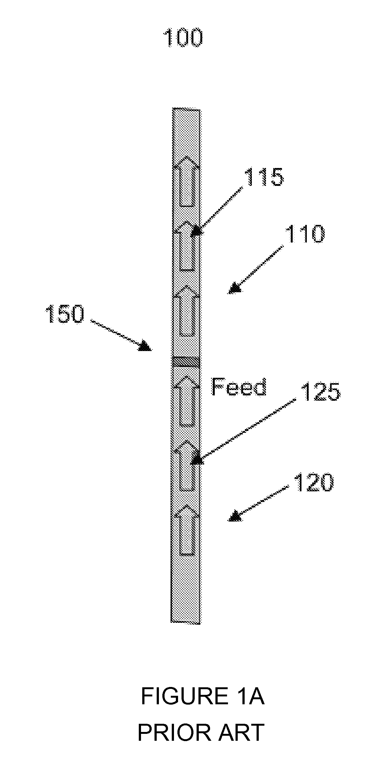
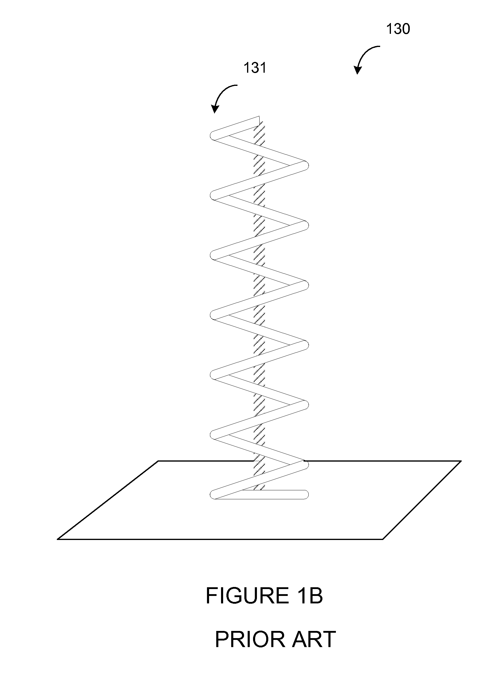
[0079]A high performance, compact volumetric antenna (e.g., “rib-dipole” or “rib-monopole” antenna) has the advantages of a traditional dipole antenna (e.g., dipole 100 as shown in FIG. 1A), but with higher performance capabilities. Advantages of a rib-dipole / monopole antenna include, for example, a monotonic, predictable and smooth impedance curve. Another advantage is the lack of erratic impedance behavior at low frequencies (e.g., as compared to the helical antenna as shown in FIG. 1B). The volumetric dipole / monopole antenna is intrinsically better matched over a wider band as compared to small helical antennas in the prior art. The rib-dipole antenna can have a pattern that can be the same pattern of a traditional dipole antenna, regardless of size. In contrast, the helical antenna changes its pattern from broadside to end-fire when frequency increases. Therefore, the rib-dipole / monopole antenna can be used for both small and intermediate frequencies (e.g., over a wider bandwidt...
PUM
 Abstract
Description
Claims
Application Information