Fatigue resistant turbine through bolt

a technology of fatigue fatigue and bolts, applied in the direction of bolts, machines/engines, fastening means, etc., can solve problems such as crack propagation, and achieve the effect of reducing the likelihood of fretting fatigue failure and increasing the residual compressive stress

Inactive Publication Date: 2015-04-23
SIEMENS AG
View PDF4 Cites 5 Cited by
  • Summary
  • Abstract
  • Description
  • Claims
  • Application Information

AI Technical Summary

Benefits of technology

[0003]This application is directed to a bolt, such as, but not limited to a fatigue resistant turbine through bolt, formed from a base material covered by a first surface modification or a second surface modification, or both. The first surface modification may be in contact with the base material and, in at least one embodiment, may be a low plasticity burnished layer that increases the residual compressive stresses on an outer surface of the turbine through bolt. The second surface modification may cover the first surface modification and, in at least one embodiment, may be a spinel oxide layer on the low plasticity burnished layer. The first surface modification may be positioned on one or more turbine through bolt contact surfaces positioned on a shaft of the turbine through bolt. The second surface modification may be positioned on the first surface modification on the turbine through bolt contact surface positioned on the shaft of the turbine through bolt. The first and second surface modifications may reduce the likelihood of fretting fatigue failures.

Problems solved by technology

Cracking has been initiated by fretting high cycle fatigue, and crack propagation has been determined to be caused by high cycle fatigue.

Method used


Image

  • Fatigue resistant turbine through bolt
  • Fatigue resistant turbine through bolt
  • Fatigue resistant turbine through bolt

Examples


Embodiment Construction

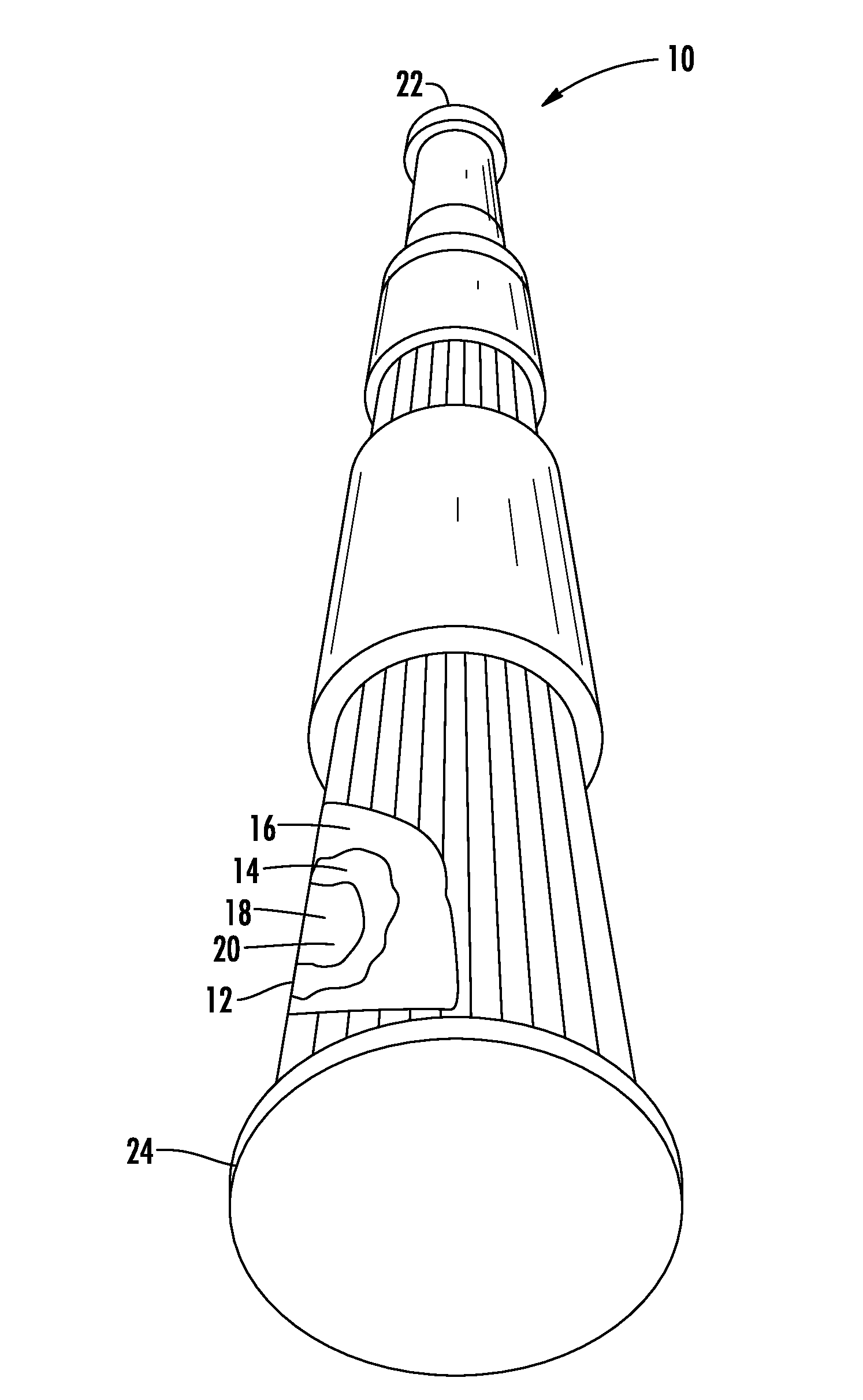
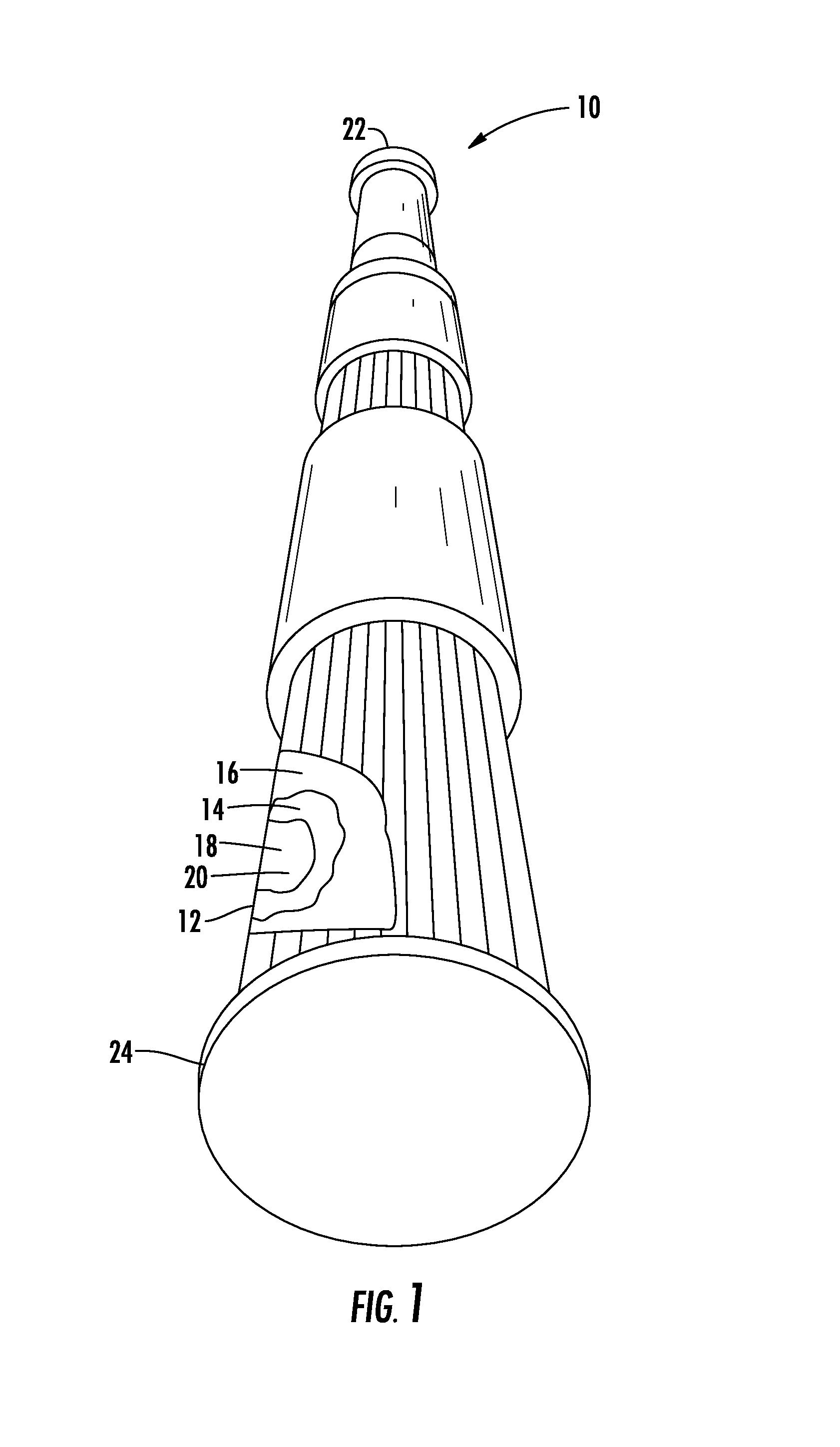
[0015]As shown in FIGS. 1-4, this invention is directed to a turbine through bolt 10, such as, but not limited to a fatigue resistant turbine through turbine through bolt 10, formed from a base material 12 covered by a first surface modification 14 or a second surface modification 16, or both. The first surface modification 14 may be in contact with the base material 12 and, in at least one embodiment, may be a low plasticity burnished layer that increases the residual compressive stresses on an outer surface 18 of the turbine through bolt 10. The second surface modification 16 may cover the first surface modification 14 and, in at least one embodiment, may be a spinel oxide layer on the low plasticity burnished layer. The first surface modification 14 may be positioned on one or more turbine through bolt contact surfaces 20 positioned on a shaft 24 of the turbine through bolt 10. The second surface modification 16 may be positioned on the first surface modification 14 on the turbin...


PUM

PropertyMeasurementUnit
thicknessaaaaaaaaaa
temperatureaaaaaaaaaa
residual compressive stressaaaaaaaaaa

Abstract

A fatigue resistant turbine through bolt formed from a base material covered by a first surface modification and a second surface modification is disclosed. The first surface modification may be in contact with the base material and, in at least one embodiment, may be a low plasticity burnished layer that increases the residual compressive stresses on an outer surface of the turbine through bolt. The second surface modification may cover the first surface modification and, in at least one embodiment, may be a spinel oxide layer on the low plasticity burnished layer. The second surface modification may be positioned on the first surface modification or on the bare turbine through bolt contact surface without low plastiocity burnishing on the shaft of the turbine through bolt. The first and second surface modifications reduce the likelihood of fretting fatigue failures.

Description

FIELD OF THE INVENTION[0001]The invention relates to one or more surface modifications on a turbine through bolt for reduced fretting fatigue crack initiation and propagation and more particularly, to a turbine through bolt having a low plasticity burnished layer or a spinel oxide layer, or both, to reduce fretting fatigue crack initiation and propagation.BACKGROUND OF THE INVENTION[0002]Turbine through bolts made of INCO 718 material have suffered from fretting high cycle fatigue failures at the through bolt seal disk contact location in industrial gas turbine engines, as shown in FIG. 1. Cracking has been initiated by fretting high cycle fatigue, and crack propagation has been determined to be caused by high cycle fatigue.SUMMARY OF THE INVENTION[0003]This application is directed to a bolt, such as, but not limited to a fatigue resistant turbine through bolt, formed from a base material covered by a first surface modification or a second surface modification, or both. The first su...

Claims


Application Information

Patent Timeline
Patent Type & Authority Applications(United States)
IPC IPC(8): F16B33/06B23P9/02
CPCB23P9/02F16B33/06C21D7/08C22C19/055C22C19/056F01D5/066C21D6/004C21D6/005C21D6/007C21D6/02C21D9/0093Y10T29/47
Inventor OZBAYSAL, KAZIMABDO, ZAFIR A. M.STARR, KENNETH K.SHINDE, SACHIN R.
Owner SIEMENS AG
Why Eureka
Try Eureka