Pneumatic system for an aircraft

a pneumatic system and aircraft technology, applied in the direction of machines/engines, transportation and packaging, machine/engine, etc., can solve the problems of increased sfc (i.e. excessive fuel burn), and achieve the effect of reducing specific fuel consumption, improving the operability of aircraft pneumatic systems, and reducing engine pressure loss

Inactive Publication Date: 2015-04-23
ROLLS ROYCE PLC
View PDF16 Cites 43 Cited by
  • Summary
  • Abstract
  • Description
  • Claims
  • Application Information

AI Technical Summary

Benefits of technology

[0019]Accordingly, the invention provides a control method and a pneumatic system in which the environmental control system (ECS) is operated in an operating mode which requires operation of a lower pressure bleed port or combination of bleed ports during some pneumatic system conditions. In order to accommodate the variable operating modes of the ECS, each of which has a corresponding pressure requirement, the system is configured to provide the necessary pressure from the lowest pressure bleed port. Both the bleed air system (BAS) and the ECS are therefore configured to operate with one another, by choosing an ECS operating mode requiring a minimum pressure, and matching delivery pressure provided by the BAS with the operating pressure required by the selected operating mode of the ECS, rather than operating these two systems independently. Consequently, the ECS and BAS are optimised with respect to one another for the current pneumatic system conditions, thereby providing improved operability of the aircraft pneumatic system, and gas turbine engine. In other words, the pressure requirement of the ECS is allowed to vary by operating the ECS in different operating modes in accordance with current pneumatic system conditions, and the controller adjusts the delivered air pressure accordingly by the most efficient method, by providing the bleed air from the lowest pressure port capable of providing the required pressure. Consequently, in some flight conditions, a lower pressure bleed port can be used than would normally be scheduled in the case of the prior art operating methods and systems, resulting in reduced engine pressure loss, and therefore reduced Specific Fuel Consumption (SFC). In one scenario, it has been found that the invention can reduce SFC by up to 1% over a typical flight cycle, and up to 4% in some parts of the flight cycle, resulting in considerable fuel saving to the aircraft operators, and reduced environmental impact.

Problems solved by technology

However, existing bleed air systems and methods for control which rely on engine compressor pressure or corrected compressor rotational speed and / or altitude may in some cases provide bleed from a higher pressure compressor stage than is necessary to fulfil the requirements of the ECS system in the mode in which it is operating, resulting in increased SFC (i.e. excessive fuel burn).

Method used


Image

  • Pneumatic system for an aircraft
  • Pneumatic system for an aircraft
  • Pneumatic system for an aircraft

Examples


Embodiment Construction

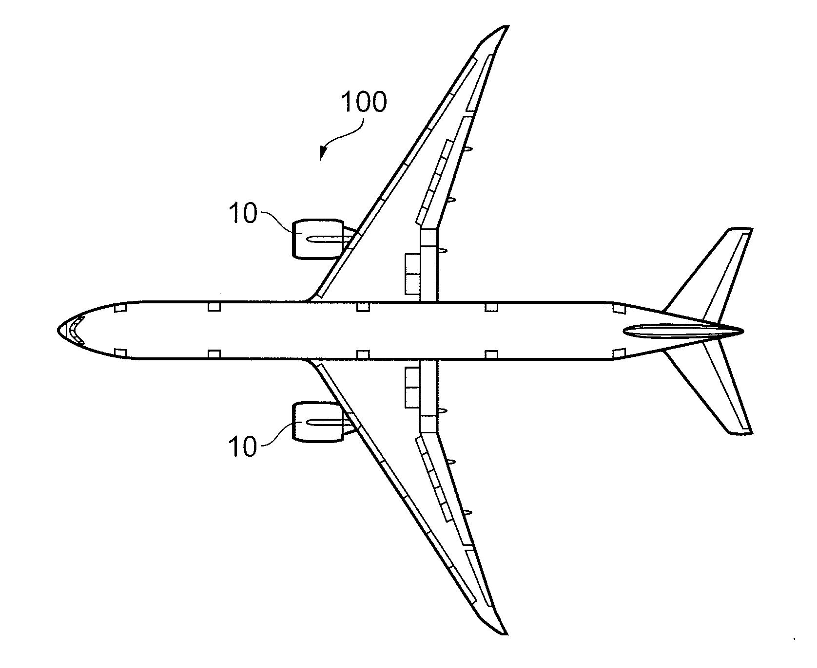
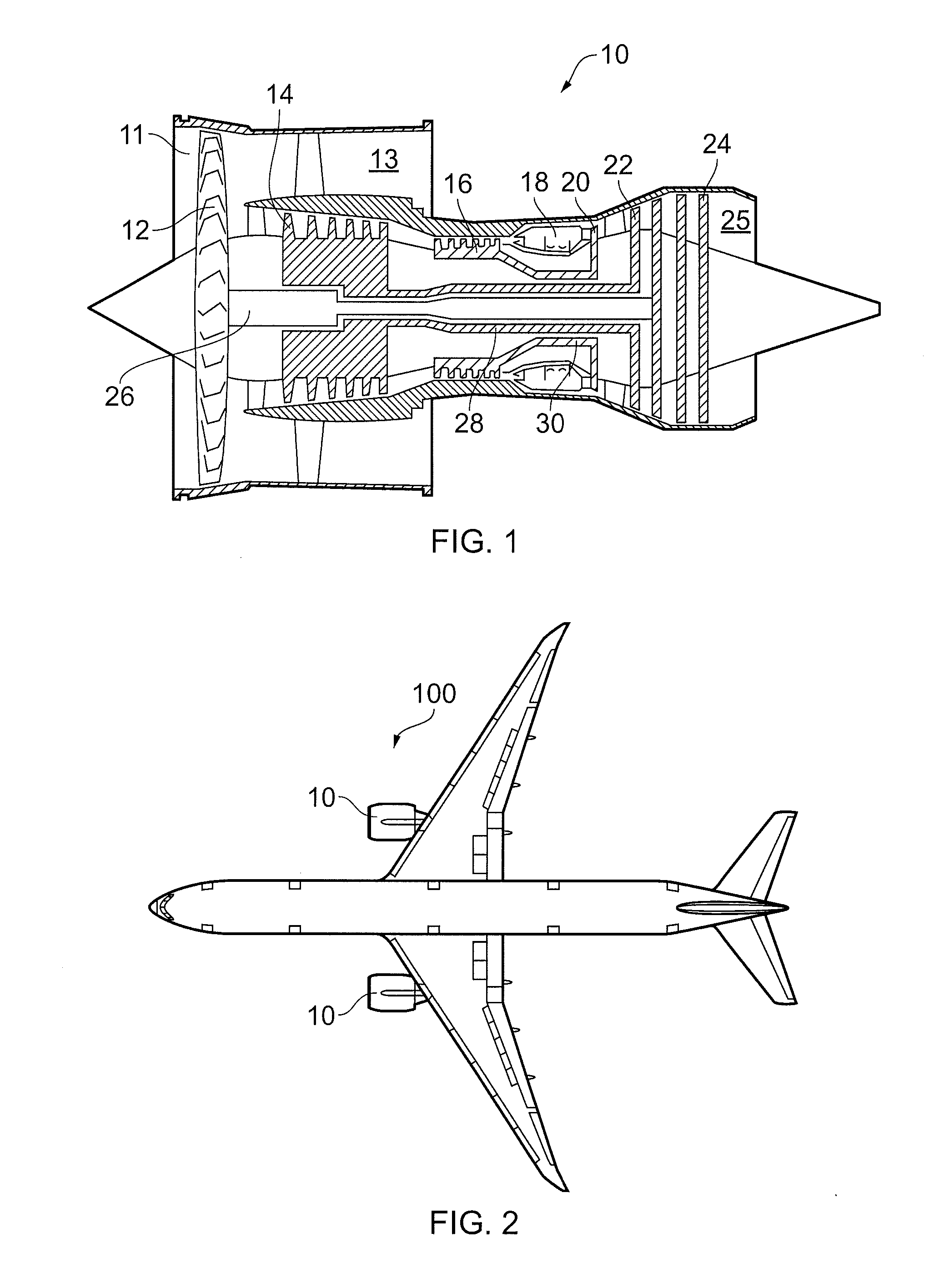
[0045]FIG. 2 shows an aircraft 100 having a pair of gas turbine engines 10 (shown in detail in FIG. 1) and an aircraft pneumatic system 110. The gas turbine engines 10 are conventional in configuration, comprising, in axial flow series, an air intake duct 11, an intake fan 12, a bypass duct 13, an intermediate pressure compressor 14, a high pressure compressor 16, a combustor 18, a high pressure turbine 20, an intermediate pressure turbine 22, a low pressure turbine 24 and an exhaust nozzle 25. Each compressor 14, 16 comprises a series of axial or centrifugal compressors, having multiple stages arranged in series, each stage pressurising air passing therethrough to a higher pressure than the previous stage.

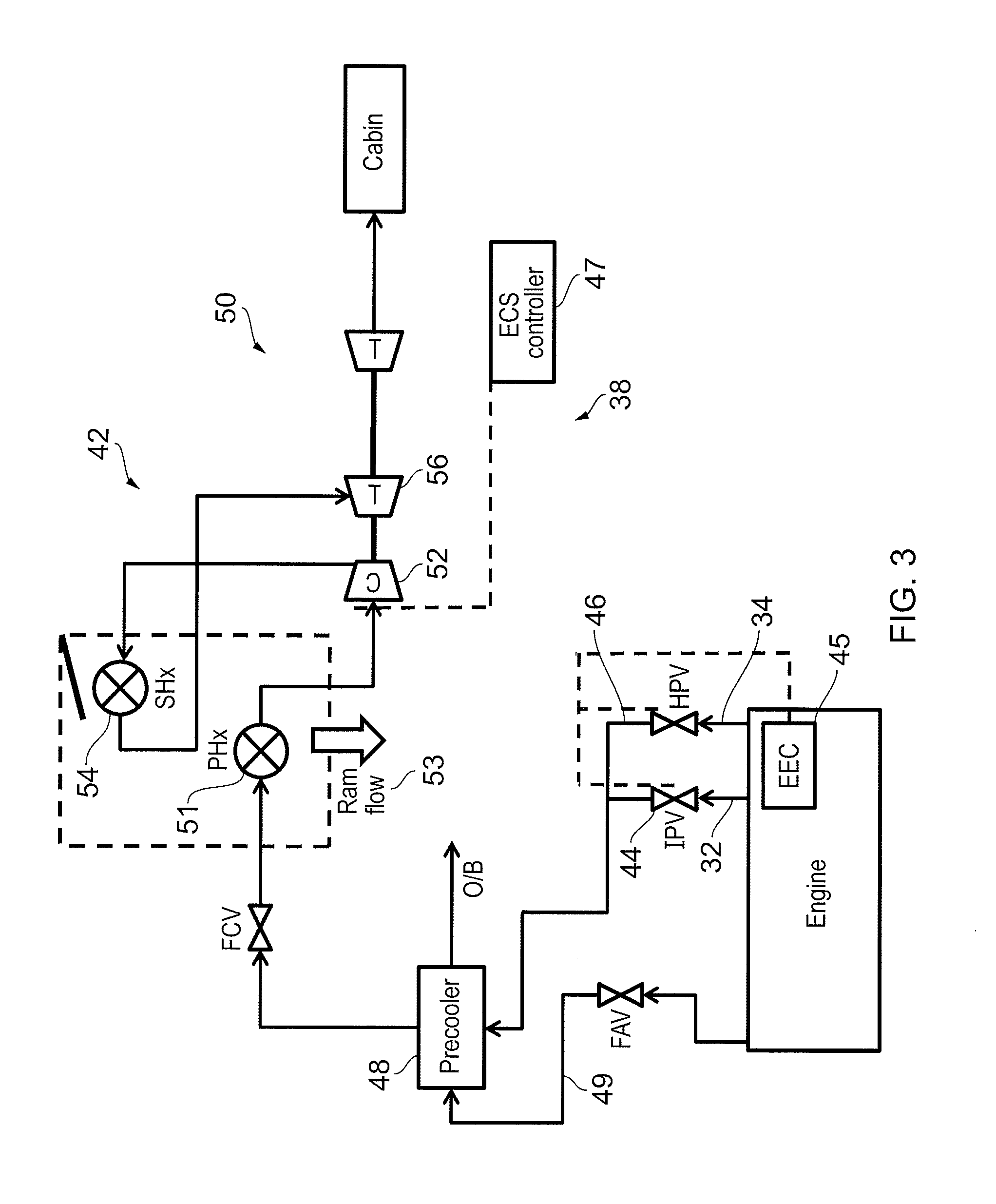
[0046]FIG. 4 shows the pneumatic system 110 in more detail. The system 110 comprises an ECS 142 which is supplied by air from a bleed air system 143. The bleed air system 143 comprises first, second and third bleed ports 132, 134, 135. Each bleed port is in fluid communication wit...


PUM


Abstract

A bleed air system for an aircraft has a gas turbine engine and operating method. The system includes an environmental control system (ECS) for providing cabin airflow to the aircraft, including operating modes such as first and second air cycle machine operating modes and heat exchanger operating modes. The ECS includes first, second and third bleed ports each configured to provide engine bleed air from gas turbine engine compressors to the ECS. The ECS includes a bleed air system sensor arrangement configured to sense one or more bleed air system conditions, an environmental control system controller that selects an environmental control system operating mode that provides required cabin air flow and temperature at an optimal specific fuel consumption of the gas turbine engine at the sensed system conditions, and a bleed port valve controller which determines an operating pressure required to operate the environmental control system in the selected mode.

Description

FIELD OF THE INVENTION[0001]The present invention relates to a pneumatic system for an aircraft, and a method of operating a pneumatic system for an aircraft.BACKGROUND TO THE INVENTION[0002]FIG. 1 shows a gas turbine engine 10. The gas turbine engine 10 is mounted on an aircraft 100 in pairs, as shown in FIG. 2. The engine 10 comprises, in axial flow series, an air intake duct 11, an intake fan 12, a bypass duct 13, an intermediate pressure compressor 14, a high pressure compressor 16, a combustor 18, a high pressure turbine 20, an intermediate pressure turbine 22, a low pressure turbine 24 and an exhaust nozzle 25. The fan 12, compressors 14, 16 and turbines 20, 22, 24 all rotate about the major axis of the gas turbine engine 10 and so define the axial direction of gas turbine engine.[0003]Air is drawn through the air intake duct 11 by the intake fan 12 where it is accelerated. A significant portion of the airflow is discharged through the bypass duct 13 generating a corresponding...

Claims


Application Information

Patent Timeline
Patent Type & Authority Applications(United States)
IPC IPC(8): B64D13/06B64D41/00B64D13/08
CPCB64D13/06B64D2013/0618B64D41/00B64D13/08B64D2013/0648Y02T50/50
Inventor MOES, THIERRYSTIEGER, RORY DOUGLASHILLEL, MALCOLM LAURENCEVYAS, PARAG
Owner ROLLS ROYCE PLC
Why Eureka
Try Eureka