
Process for producing chemically strengthened glass

a technology of chemical strengthening glass and glass, which is applied in the direction of glass tempering apparatus, instruments, casings/cabinets/drawers details, etc., can solve the problems of increasing the number of steps and the cost, affecting the appearance of the device, and only passing a small portion of light, etc., and achieves excellent shielding properties, high strength, and low cost.

Active Publication Date: 2015-04-23
ASAHI GLASS CO LTD
View PDF3 Cites 37 Cited by
  • Summary
  • Abstract
  • Description
  • Claims
  • Application Information

AI Technical Summary

Benefits of technology

The present invention provides a process for producing chemically strengthened glass with excellent shielding properties suitable for electronic device housings, without the need for additional light shielding measures. The glass itself exhibits a milky white appearance, which can be achieved even when multiple white coating film layers are laminated. The chemically strengthened glass obtained through this process also exhibits excellent scratch resistance compared to crystallized glass. The production process involves allowing the glass to exhibit white through phase-separation and then chemically strengthening it with low-temperature ion exchange treatment, resulting in a whitened, chemically strengthened glass with improved resistance to scratch. This process is cost-effective and efficient, making it suitable for use in electronic device housings.

Problems solved by technology

When a metal is used as a material of a housing, such a problem is not caused.
As described above, in accordance with high luminance of the light source in the display device, it is necessary to form a thick film or a film formed of a plurality of layers as a coating film in order to form the coating film with a sufficient shielding property on the rear surface (device side) of glass, and this results in increasing the number of steps and the cost.
Further, in a case where the coating film is not uniformly formed, there is a concern that light is transmitted through only a portion whose coating film is thin and the appearance of the device may be impaired, for example, such that the housing is recognized to be locally bright.
However, a step of uniformly forming a coating film having a sufficient shielding property on a concave surface is complicated and this results in increasing the cost.
However, since a white coating material has high translucency, a sufficient shielding property cannot be obtained even when the white coating film layer is made thick.
In this manner, when a housing having a high shielding property, which exhibits white using a white coating material, is obtained, there is a problem that the cost thereof is extremely high.

Method used


Image

  • Process for producing chemically strengthened glass
  • Process for producing chemically strengthened glass
  • Process for producing chemically strengthened glass

Examples


example 1

(1) Heat Treatment (Phase-Separation Treatment)

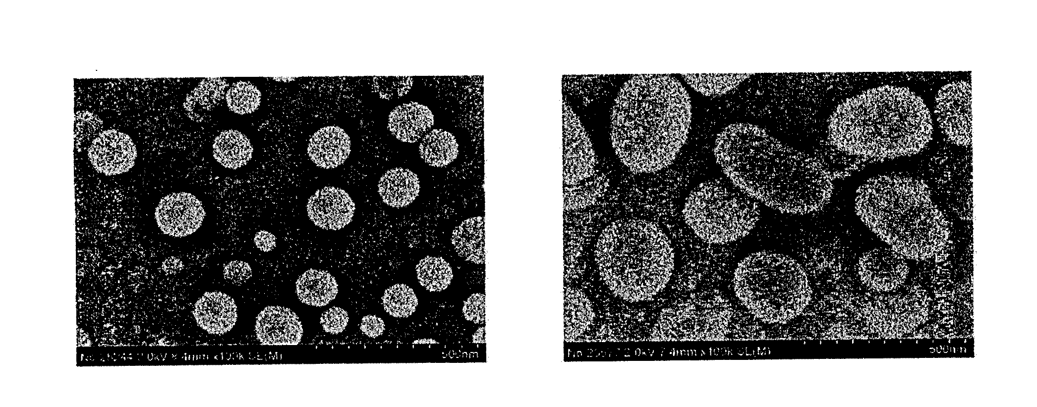
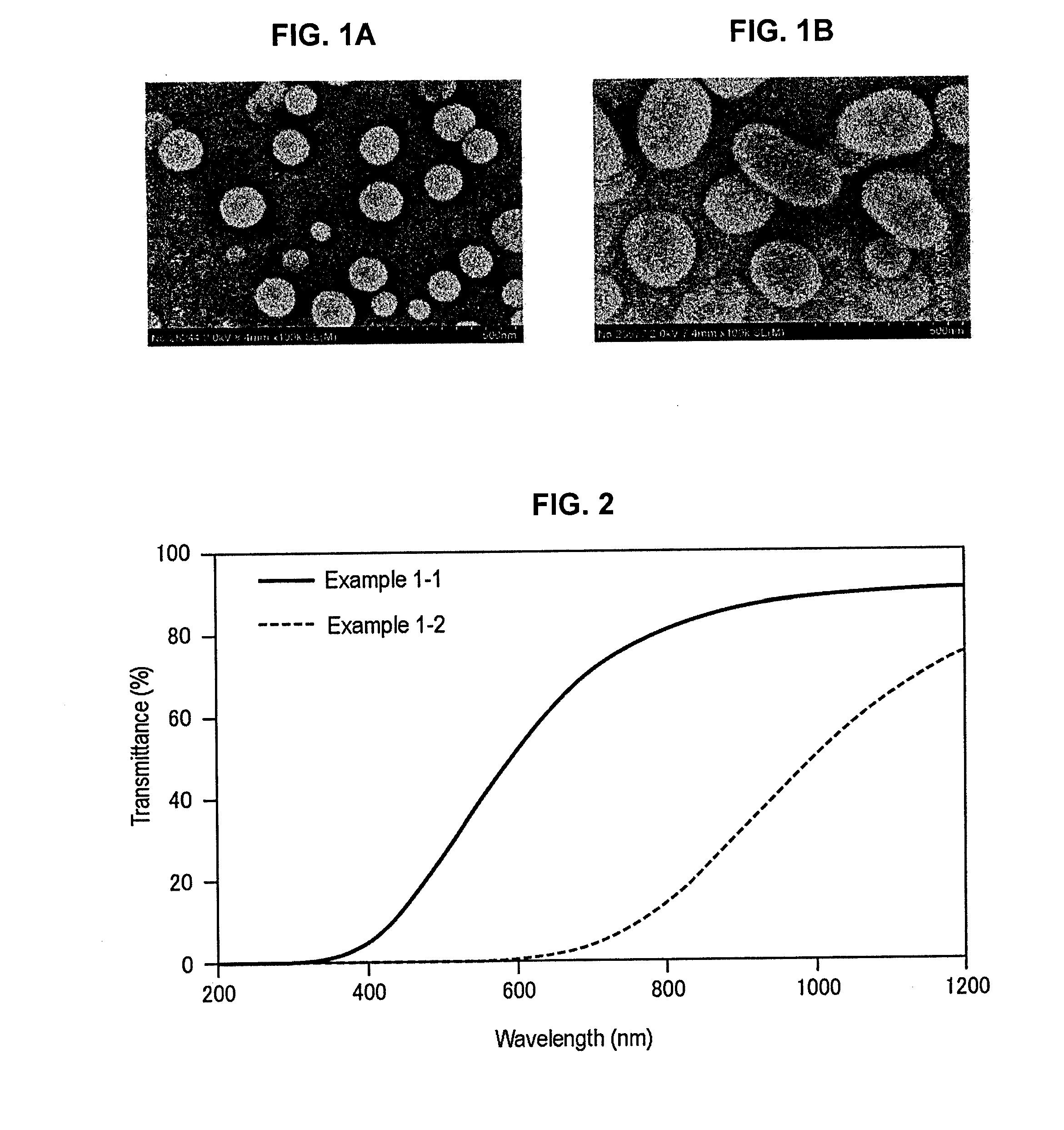
[0173]A raw material having a composition listed in Table 1 was melted at a temperature of 1650° C. and a sample which was annealed at 730° C. was subjected to a heat treatment. Sodium sulfate having a mass corresponding to 0.1% to 0.4% of the mass was added to the composition listed in Table 1. The mixture was subjected to heat treatment at 900° C. for 4 hours and the phase-separation of the glass was observed using a SEM. The results are shown in FIGS. 1A-1B. FIG. 1A illustrates results of Example 1-1 and FIG. 1B illustrates results of Example 1-2.

[0174]As illustrated in FIGS. 1A-1B, phase-separation occurred in both of Examples 1-1 and 1-2 to thereby obtain a milky white sample. The composition of Example 1-2 was obtained by adding 1 mol % of P2O5 to the case of Example 1-1, but phase-separation occurred at the time when a melt was flown out and whiteness was drastically increased as compared to the case of Example 1-1 by further per...

example 2

(1) Phase-Separation Treatment (Heat Treatment)

[0181]A raw material having a composition listed in Tables 2 to 4 was melted at a temperature of 1650° C. and a sample which was annealed at an annealing temperature listed in Tables 2 to 4 was subjected to a heat treatment and then phase-separated under the conditions listed in Tables 2 to 4. Further, a sample phase-separated in a step of melting, molding, or annealing was described as “non-treated.” The results of measuring transmittance of the obtained sample were shown in Tables 2 to 4 and FIGS. 5A-5C. Moreover, the results of observing the phase-separation state using a SEM were shown in Tables 2 to 4.

[0182]Further, in regard to Examples 2-3, 2-6, and 2-7, the heat treatment for phase-separation was not performed, but the glass was phase-separated with whiteness due to the heat treatment for melting the glass to obtain low transmittance. In addition, the sample of Example 2-2 was the same as the sample of Example 1-1 and the sample...

example 3

[0186]The glass described below was used as crystallized glass, phase-separated glass (binodal), or reference glass.

[0187](1) Crystallized Glass

[0188]The glass having a composition of 50.4% of SiO2, 22.7% of Al2O3, 6.9% of TiO2, 12.5% of Na2O, and 7.5% of K2O as represented by mol % basis was subjected to the heat treatment at 850° C. for 4 hours, and then, the glass which was subjected to the heat treatment at 1100° C. for 4 hours, thereby obtaining crystallized glass.

[0189]The crystallized glass was chemically strengthened through the ion exchange treatment with KNO3 at 450° C. for 30 hours.

[0190](2) Phase-Separated Glass

[0191]The glass having a composition of 59.7% of SiO2, 3.3% of Al2O3, 3.9% of B2O3, 14.9% of MgO, 4.1% of ZrO2, 9.1% of Na2O, and 5.0% of P2O5 as represented by mol % was subjected to the heat treatment at 900° C. for 4 hours, thereby obtaining phase-separated glass.

[0192]The phase-separated glass was chemically strengthened through the ion exchange treatment with...


PUM

PropertyMeasurementUnit
Weightaaaaaaaaaa
Weightaaaaaaaaaa
Timeaaaaaaaaaa

Abstract

A process for producing a chemically strengthened glass is provided. The method for producing a chemically strengthened glass includes subjecting a phase-separated glass to an ion exchange treatment. A chemically strengthened glass which is obtained by the process and a phase-separated glass which has been subjected to the ion exchange treatment are also provided.

Description

TECHNICAL FIELD[0001]The present invention relates to a process for producing chemically strengthened glass to be favorably used as an exterior member of electronic device such as communication device or information device which can be used by being carried.BACKGROUND ART[0002]In a housing of electronic device such as a mobile phone, a method appropriately selected from materials of resins or metals is used in consideration of various factors such as decoration properties, scratch resistance, workability, and cost. In recent years, glass which has not been used in the related art has been attempted to be used as a material of a housing (Patent Document 1). According to Patent Document 1, in the electronic device such as a mobile phone, it is possible to exhibit a distinctive decorative effect with a transparency feeling by forming a main body of the housing with glass.[0003]Electronic device includes a display device such as a liquid crystal panel on the outer surface of the device....

Claims


Application Information

Patent Timeline
IPC IPC(8): C03C21/00H05K5/03C03C23/00
CPCC03C21/002H05K5/03C03C23/007Y10T428/268Y10T428/315
Inventor MIYASAKA, JUNKOSAKAGAMI, TAKAHIROOHARA, SEIKIAKATSUKA, KOSHOREYES, MANUEL DIAZONO, KAZUTAKAHIJIYA, HIROYUKI
Owner ASAHI GLASS CO LTD
Learn More