Fuel cell system

a fuel cell and system technology, applied in the field of fuel cell systems, can solve the problems of reducing the effective area and deteriorating the output characteristics, and achieve the effect of minimizing the influence of responsiveness and maximizing the performance recovery of the catalyst layer

Active Publication Date: 2015-04-23
TOYOTA JIDOSHA KK
View PDF1 Cites 8 Cited by
  • Summary
  • Abstract
  • Description
  • Claims
  • Application Information

AI Technical Summary

Benefits of technology

[0018]The present invention can provide a fuel cell system capable of maximizing the performance recovery of a catalyst layer while minimizing the influence on responsiveness to an output increase request.

Problems solved by technology

In fuel cell systems of this type, when a cell continues to be operated within an operation zone where the cell voltage reaches an oxidation voltage (about 0.7 V to 1.0 V), an oxide film may be formed on a surface of the platinum catalyst in the catalyst layer and reduce an effective area of the platinum catalyst, which may cause degradation of output characteristics.

Method used


Image

  • Fuel cell system
  • Fuel cell system
  • Fuel cell system

Examples


embodiment 1

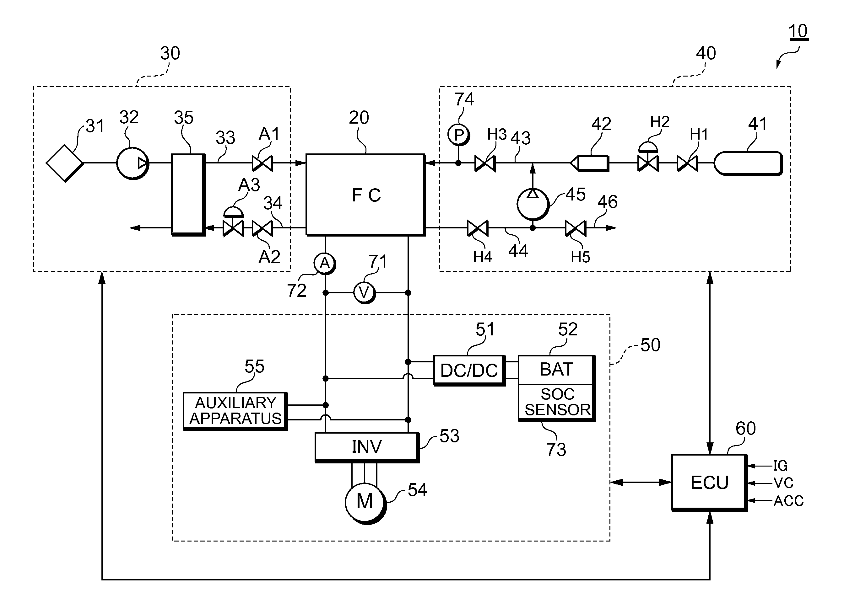
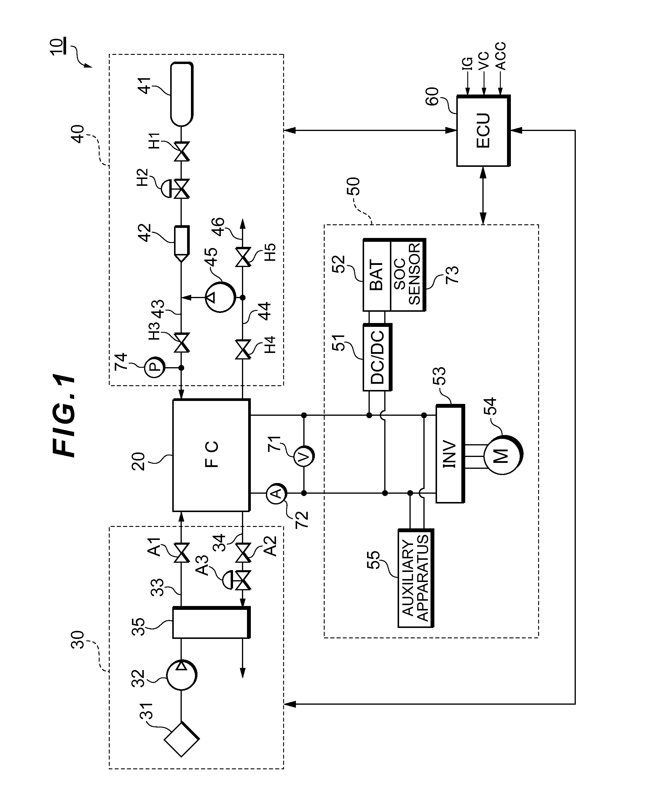
[0034]FIG. 1 illustrates the system configuration of a fuel cell system 10 according to Embodiment 1.

[0035]The fuel cell system 10 serves as an in-vehicle power supply system that is installed in a fuel cell vehicle and includes: a fuel cell stack 20 which receives supply of reactant gases (a fuel gas and an oxidant gas) and generates electric power; an oxidant gas supply system 30 for supplying the air serving as the oxidant gas to the fuel cell stack 20; a fuel gas supply system 40 for supplying a hydrogen gas serving as the fuel gas to the fuel cell stack 20; a power system 50 for controlling charge and discharge of electric power; and a controller 60 which controls the entire system.

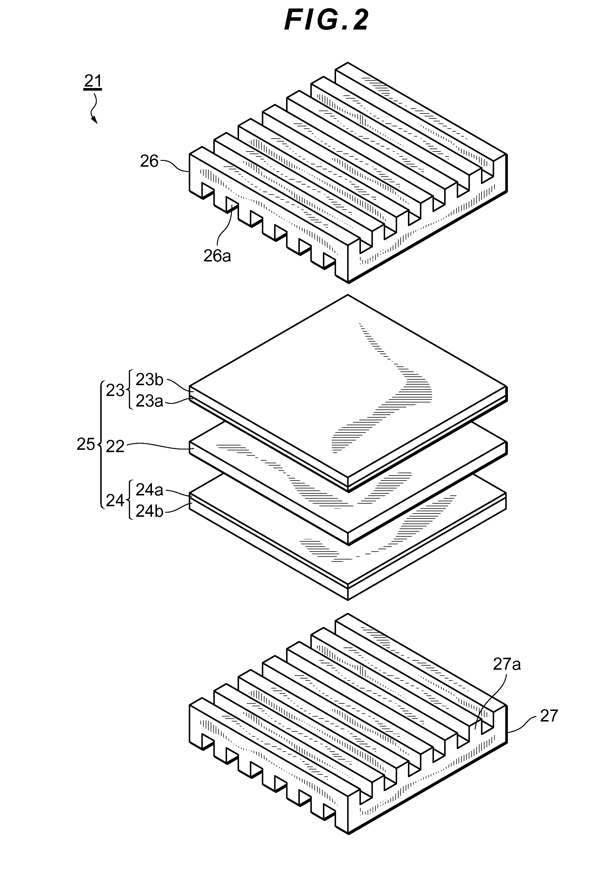
[0036]The fuel cell stack 20 is a solid polymer electrolyte-type cell stack in which a plurality of cells are stacked in series. In the fuel cell stack 20, the oxidation reaction in formula (1) occurs in an anode and the reduction reaction in formula (2) occurs in a cathode. The electrogenic reaction...

embodiment 2

[0076]FIG. 5 is a flowchart showing the procedure for performing the refresh processing when the degree of braking exceeds a predetermined threshold, in accordance with such degree of braking.

[0077]FIGS. 6 and 7 each show an example of the refresh processing shown in FIG. 5 performed according to the degree of braking. FIG. 6 is a table showing the relationship between the degree of braking and a refresh voltage and FIG. 7 is a table showing the relationship between the degree of braking and a refresh time period.

[0078]The flowchart shown in FIG. 5 will now be described. Since steps S1 to S5 in FIG. 5 are the same processes as steps S1 to S5 in FIG. 4, these steps are given the same numbers and the descriptions thereof will be omitted here. The process of step S17, which follows step S5, will be described in detail below.

[0079]In the refresh processing performed in step S7 in FIG. 4, the refresh voltage and the refresh time period are each set to a constant value, regardless of the ...


PUM

PropertyMeasurementUnit
oxidation voltageaaaaaaaaaa
reduction voltageaaaaaaaaaa
output voltageaaaaaaaaaa

Abstract

A fuel cell system according to the present invention comprises: a fuel cell including a membrane-electrode assembly in which electrodes, each having a catalyst layer, are arranged on both surfaces of a polymer electrolyte membrane; and a control apparatus that performs performance recovery processing for the catalyst layer by decreasing an output voltage of the fuel cell to a predetermined voltage, wherein the control apparatus predicts a timing of an output increase request being made to the fuel cell and determines the necessity and content of the performance recovery processing based on a result of the prediction.

Description

TECHNICAL FIELD[0001]The present invention relates to a fuel cell system having a function of activating a catalyst.BACKGROUND ART[0002]A fuel cell stack is a power generation system which oxidizes a fuel through an electrochemical process to thereby directly convert energy released due to such oxidization reaction into electric energy. Such fuel cell stack has a membrane-electrode assembly in which a polymer electrolyte membrane, which selectively transports hydrogen ions, is sandwiched by a pair of electrodes made of porous materials. Each of the pair of electrodes includes: a catalyst layer that contains, as a main ingredient, carbon powder supporting a platinum-based metal catalyst and contacts with the polymer electrolyte membrane; and a gas diffusion layer formed on a surface of the catalyst layer, the gas diffusion layer having both air permeability and electronic conductivity.[0003]In fuel cell systems of this type, when a cell continues to be operated within an operation zo...

Claims


Application Information

Patent Timeline
Patent Type & Authority Applications(United States)
IPC IPC(8): H01M8/04H01M8/10
CPCH01M8/04992H01M2250/20H01M2008/1095H01M8/10H01M8/04238H01M8/0488H01M8/04559H01M8/04589H01M8/04753Y02T90/40Y02E60/50
Inventor MATSUSUE, MASAAKIIKEDA, KOTARO
Owner TOYOTA JIDOSHA KK
Why Eureka
Try Eureka