Pump control apparatus for fuel supply system of fuel-injection engine

a technology of pump control apparatus and fuel injection engine, which is applied in the direction of electrical control, process and machine control, instruments, etc., can solve the problems of excessive quantity values of necessary delivery, common rail pressure may overshoot the target pressure value, and may hunt, etc., and achieve accurate fuel consumption quantity values

Inactive Publication Date: 2015-04-23
DENSO CORP
View PDF9 Cites 13 Cited by
  • Summary
  • Abstract
  • Description
  • Claims
  • Application Information

AI Technical Summary

Benefits of technology

[0020]It can thereby be ensured that accurate values of fuel consumption quantity can be estimated even when a fuel injector is functioning abnormally. This ensures that an appropriate command quantity of fuel can be reliably impelled to the common rail from the fuel supply pump after each injection timing. The common rail pressure can thereby be reliably set at the target pressure value prior to each injection timing.

Problems solved by technology

However with such a type of control apparatus, when the target pressure value becomes changed due to a change in the running conditions of the engine, the common rail pressure may overshoot the target pressure value, or hunting may occur.
If each value of necessary delivery quantity is estimated based on a corresponding estimated fuel consumption quantity, then the necessary delivery quantity values will be excessively large.
Thus, accurate feedback control of the quantities of fuel delivered to the common rail from the fuel supply pump will not be possible.
While an assumed relationship between a total quantity of fuel injected by all of the fuel injectors of the engine and a corresponding total quantity of fuel required to be supplied to the common rail for maintaining the common rail pressure at a target pressure value may be valid, it is not necessarily appropriate for determining the relationship between each fuel consumption quantity of an individual injector and the corresponding quantity of fuel required to be delivered into the common rail, for maintaining the common rail pressure at the target pressure value.
Thus it might not be possible to maintain the common rail pressure at the target pressure value, if the method proposed in reference 1 were to be applied to the problem of possible failure of a fuel injector of an engine.

Method used


Image

  • Pump control apparatus for fuel supply system of fuel-injection engine
  • Pump control apparatus for fuel supply system of fuel-injection engine
  • Pump control apparatus for fuel supply system of fuel-injection engine

Examples


Embodiment Construction

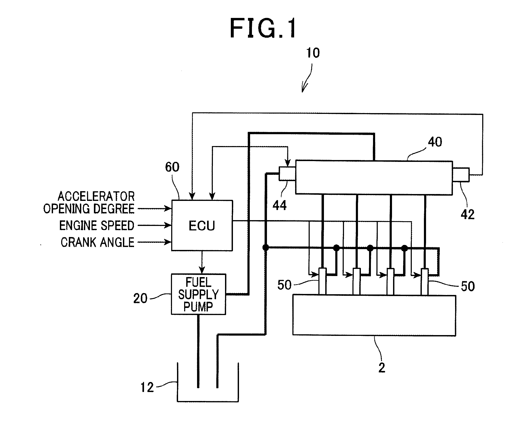
[0030]FIG. 1 is a block diagram showing the general configuration of an embodiment of a fuel supply system, designated by numeral 10. The fuel supply system 10 injects fuel into respective cylinders of an engine 2, which is a 4-cylinder diesel engine of a vehicle. As shown the fuel supply system 10 includes a fuel supply pump 20, a common rail 40, a fuel injector 50 and a ECU 60.

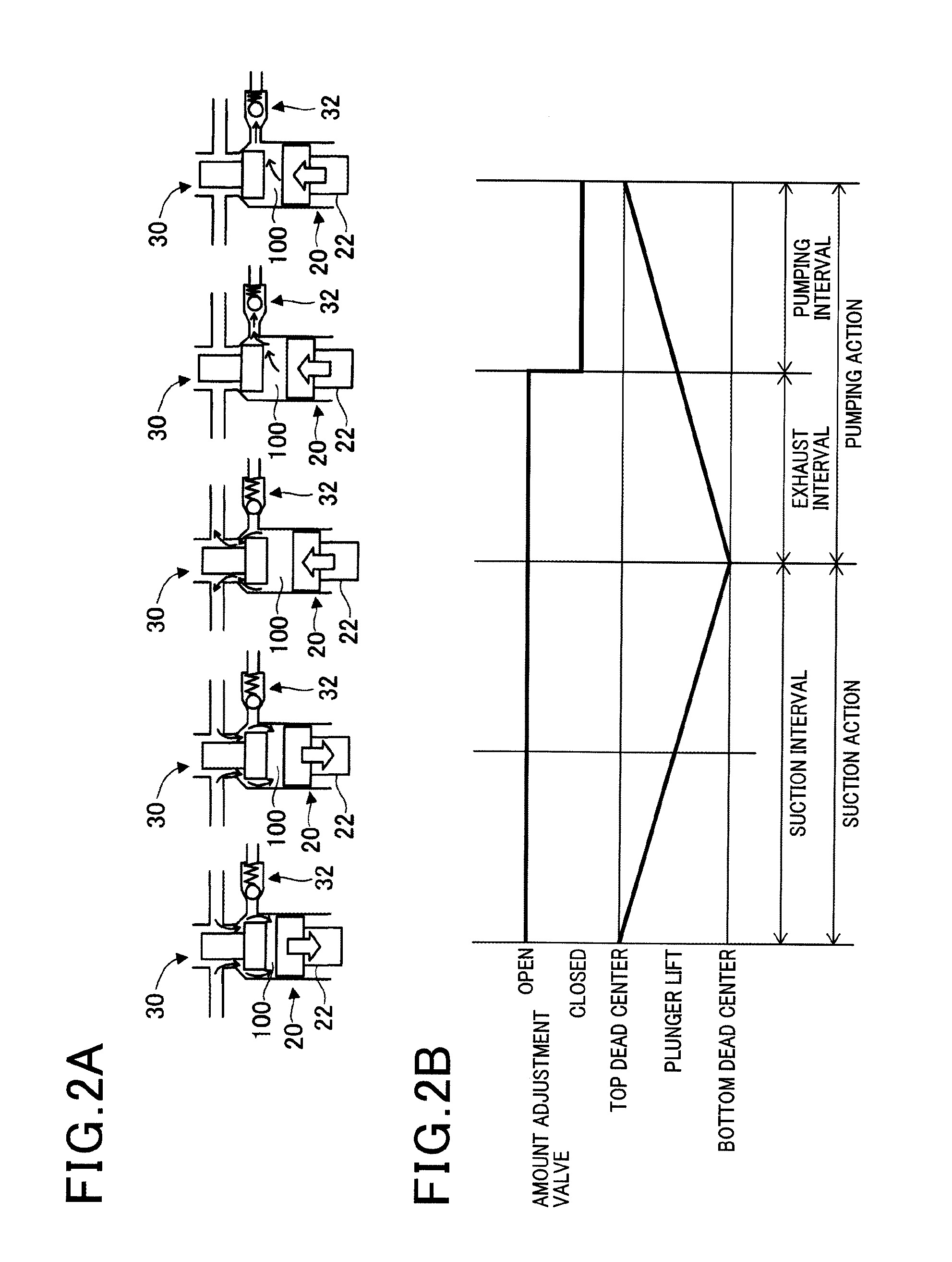
[0031]The fuel supply pump 20 incorporates a feed pump which withdraws fuel from a fuel tank 12. The operation of the fuel supply pump 20 is illustrated in FIGS. 2A and 2B. A plunger22 of the fuel supply pump 20 performs reciprocating motion within a pressure chamber 100, actuated by a cam (not shown in the drawings) which is mounted on a camshaft that is driven from the crankshaft of the engine 2. Fuel is thereby alternately drawn into the pressure chamber 100 of the fuel supply pump 20 from the feed pump, then impelled from the pressure chamber 100 into the common rail 40. An interval corresponding to one ...


PUM


Abstract

An estimated fuel consumption quantity corresponding to a fuel injection timing of an engine is reduced or set to zero if failure of the corresponding injector has been detected. A pump control apparatus controls a fuel supply pump to maintain the pressure in a common rail at a target value by control of a command delivery quantity supplied from the pump to the common rail in correspondence with each injection timing. Each command delivery quantity is determined based on a necessary delivery quantity and on a feedback quantity, which is derived from a difference between previously obtained values of command delivery quantity and of a corresponding actual delivery quantity from the pump. Prior to the injection, a pressure compensation quantity is calculated, as a fuel quantity required to bring the fuel rail pressure to the target pressure value, and is added to the fuel consumption quantity to obtain the necessary delivery quantity.

Description

CROSS-REFERENCE TO RELATED APPLICATIONS[0001]This application is based on and incorporates herein by reference Japanese Patent First Application No. 2013-219221 filed on Oct. 22, 2013.BACKGROUND OF THE INVENTION[0002]1. Field of Application[0003]The present invention relates to a pump control apparatus for application to a fuel supply system of an internal combustion engine (referred to in the following simply as an engine), whereby fuel is delivered from a fuel supply pump to be stored under pressure in a common rail, and supplied from the common rail to respective fuel injectors of the engine cylinders.[0004]2. Description of Related Art[0005]With such a fuel supply system, the fuel supply pump (high-pressure fuel pump) repetitively impels a controlled quantity of fuel (referred to in the following as a pumping quantity) into the common rail. Types of control apparatus for such a fuel supply system are known whereby the fuel pressure within the common rail (referred to in the foll...

Claims


Application Information

Patent Timeline
Patent Type & Authority Applications(United States)
IPC IPC(8): F02D41/38F02D41/14
CPCF02D41/1401F02D41/3845F02D41/0087F02D41/123F02D41/221F02D2041/225
Inventor WATANABE, KAZUMASA
Owner DENSO CORP
Why Eureka
Try Eureka