
Gas sensor element, gas sensor, and method of manufacturing gas sensor element

a technology of gas sensor and sensor element, which is applied in the direction of instruments, structural/machine measurement, coatings, etc., can solve the problems of increasing the time required for activating the sensor element, increasing the power consumption of the heater, and affecting the quality of the produ

Active Publication Date: 2015-04-30
NGK SPARK PLUG CO LTD
View PDF4 Cites 11 Cited by
  • Summary
  • Abstract
  • Description
  • Claims
  • Application Information

AI Technical Summary

Benefits of technology

The present invention provides a gas sensor element with a protection layer that is smaller in heat capacity than a conventional protection layer formed by dipping. The protection layer is formed by a spraying process using slurry, which reduces the amount of slurry wasted and the time required for spraying. However, the spraying process may lead to waste of slurry and increased power consumption of the heater. The invention proposes a solution by providing a separation portion in the forward region of the element body, which allows for temporary accumulation of water and reduces the likelihood of breakage of the element body. The protection layer is laminated together without the separation portion in the rear region, restraining deterioration in adhesion between the protection layer and the element body. Overall, the invention provides a gas sensor element with a smaller heat capacity and lower power consumption.

Problems solved by technology

However, the above-mentioned dipping process involves the following problem: since the protection layer reduces in thickness at particular portions (particularly, in the vicinity of four vertexes of the forward end of the element body), in order to secure a sufficient thickness of the protection layer at those particular portions, dipping must be performed a plurality of times.
Thus, the overall volume of the protection layer increases; accordingly, heat capacity of the protection layer increases, resulting in a wasteful increase in power consumption of a heater, along with an increase in time required for activating the sensor element.
However, the spraying process is apt to involve waste of slurry; specifically, since slurry is sprayed in the form of mist, some slurry drops without being applied to the element body.
Also, the spraying process involves the following problem: since the amount of spraying per unit time is small, and thus working time of spraying becomes long, the step of forming the protection layer becomes troublesome.

Method used


Image

  • Gas sensor element, gas sensor, and method of manufacturing gas sensor element
  • Gas sensor element, gas sensor, and method of manufacturing gas sensor element
  • Gas sensor element, gas sensor, and method of manufacturing gas sensor element

Examples


first embodiment

1. First Embodiment

1-1. Overall Configuration

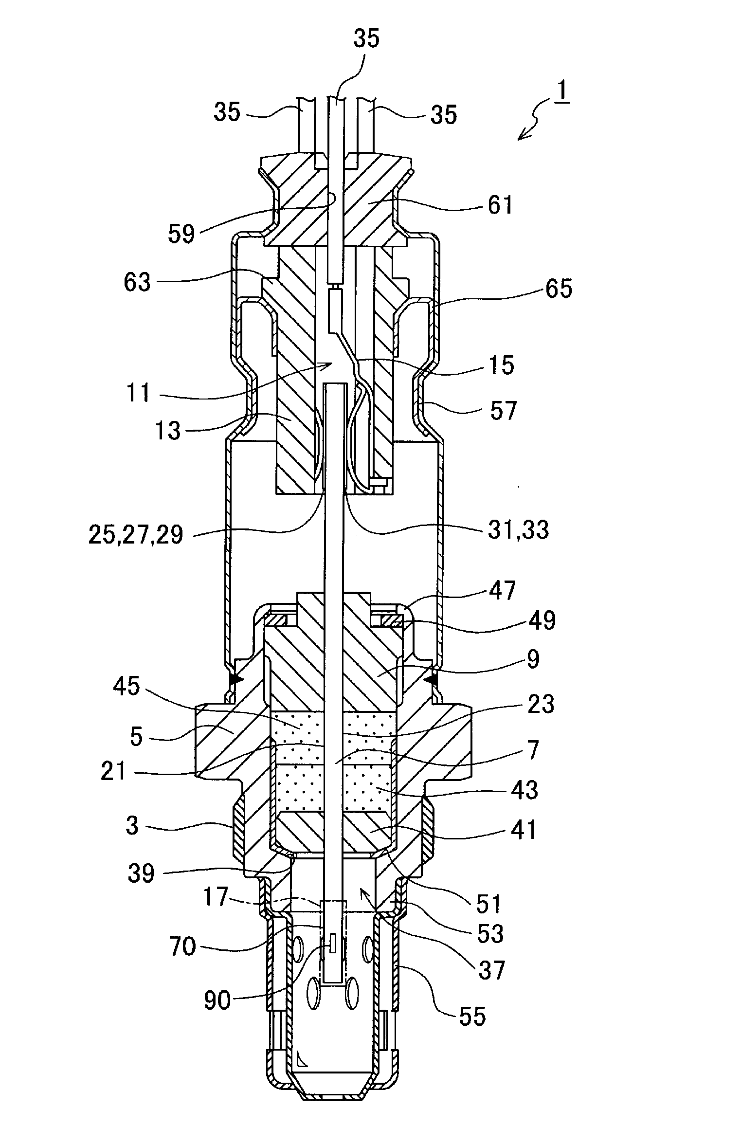
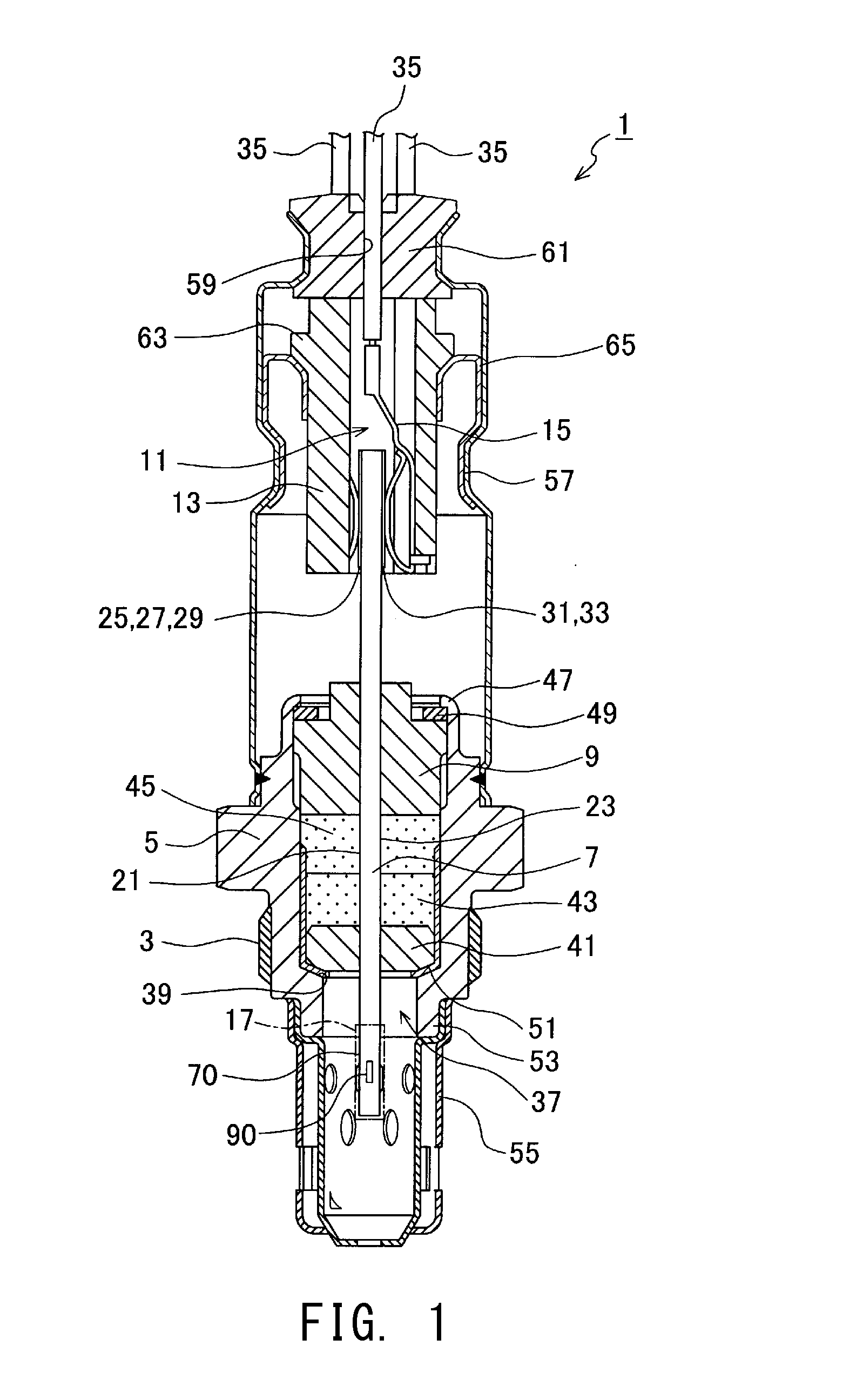
[0070]The overall configuration of an air / fuel ratio sensor which uses a gas sensor element of the present embodiment will be described with reference to FIG. 1. FIG. 1 is a sectional view showing the internal configuration of the air / fuel ratio sensor.

[0071]As shown in FIG. 1, an air / fuel ratio sensor 1 of the present embodiment includes a tubular metallic shell 5 having a threaded portion 3 formed on its outer surface and adapted to fix it to an exhaust pipe; a plate-like gas sensor element 7 extending in an axial direction (a longitudinal direction of the air / fuel ratio sensor 1, a vertical direction in FIG. 1); a tubular ceramic sleeve 9 disposed in such a manner as to radially surround the gas sensor element 7; an insulating contact member 13 (separator 13) which has an insertion hole 11 extending therethrough in the axial direction and which is disposed such that the inner wall surface of the insertion hole 11 surrounds a rear end p...


PUM


Abstract

A gas sensor element in an air / fuel ratio sensor includes an element body and a protection layer having two layers (a first layer and a second layer). The gas sensor element has at least one separation portion in the form of a space between the first layer and the second layer. The gas sensor element can temporarily accumulate, in the at least one separation portion, water which adheres to the surface of the protection layer and penetrates into the protection layer. Thus, as compared with a protection layer which is identical in thickness to the protection layer, but does not have separation portions, water adhering to the protection layer is less likely to reach the element body. Therefore, there can be restrained breakage of an end of the element body which could otherwise result from thermal shock stemming from adhesion of water.

Description

CROSS REFERENCE TO RELATED APPLICATIONS[0001]The present application claims priority to Japanese Patent Application No. 2013-224286, which was filed on Oct. 29, 2013, the disclosure of which is herein incorporated by reference in its entirety.BACKGROUND OF THE INVENTION[0002]1. Field of the Invention[0003]The present invention relates to a gas sensor element for detecting a particular gas contained in gas to be measured, a gas sensor having the gas sensor element, and a method of manufacturing the gas sensor element.[0004]2. Description of Related Art[0005]A conventionally known gas sensor having a gas sensor element for detecting a particular gas contained in gas to be measured is, for example, an oxygen sensor installed in an exhaust flow path, such as an exhaust pipe, of an internal combustion engine and utilized in controlling combustion of the internal combustion engine through detection of an oxygen concentration in exhaust gas. The oxygen sensor has, for example, a tubular me...

Claims


Application Information

Patent Timeline
IPC IPC(8): G01N33/00B05D1/36B05D3/02G01M15/10
CPCG01N33/0009G01N33/0036B05D3/0254B05D1/36G01M15/104G01N27/4077G01N27/4078
Inventor ONKAWA, MASAKISAKUMA, SHUNIWANO, TORUMURAOKA, TATSUHIKOOHTSUKA, SHIGEHIROMIZUTANI, MASAKI
Owner NGK SPARK PLUG CO LTD
Learn More