Rotating electric machine

a technology of rotating electric machines and motors, which is applied in the direction of dynamo-electric machines, structural associations, supports/enclosed/casings, etc., can solve the problems of increased manufacturing costs controller sections and/or motor sections, and insufficient dust-proof and water-proof performance of motor sections, etc., to achieve simplified structure of rotating electric machines, reduced number of parts, and simple configuration

Inactive Publication Date: 2015-04-30
DENSO CORP
View PDF2 Cites 7 Cited by
  • Summary
  • Abstract
  • Description
  • Claims
  • Application Information

AI Technical Summary

Benefits of technology

[0015]In the present disclosure, the cover extends in an axial direction of the stator, and seamlessly covers the controller section and the motor section. That is, for example, no gap space, such as a joint, is formed at a position between the controller section and the motor section in the middle of an axially-extending cover. Therefore, under the cover of such seamlessly-formed cover, intrusion of dust, water, etc., into the motor section and the controller section is effectively prevented. Further, in comparison to the separate covering of the conventional art that uses two separate parts for the covering of the motor section and the controller section, the number of parts is decreased, and the structure of the rotating electric machine is simplified. Therefore, dust / water / rust-proof character of the motor section and the controller section is provided by the present disclosure with simpler configuration. Thus, without causing a manufacturing cost increase, while controlling malfunction of the motor section and the controller section, rust generation in the motor section and the controller section is prevented.

Problems solved by technology

However, in the rotating electric machine of the patent document 1, covering the motor section and the controller section separately is not dust-proof and water-proof.
When dust or water intrudes into the controller section or the motor section, the controller section and / or the motor section may malfunction or rust may be generated therein on a metal part.
However, when the sealing member is disposed at such position, the manufacturing cost of the rotating electric machine may increase.
Further, even when a sealing member is disposed, a gap still exists between the motor case and the cover, which leaves a possibility of dust / water intrusion.
In such configuration, when glue used to seal a gap between the connector and the opening of the cover is not sufficiently sealed, dust, water, etc., may intrude into the controller section through the gap between the connector and the cover.

Method used


Image

  • Rotating electric machine
  • Rotating electric machine
  • Rotating electric machine

Examples


first embodiment

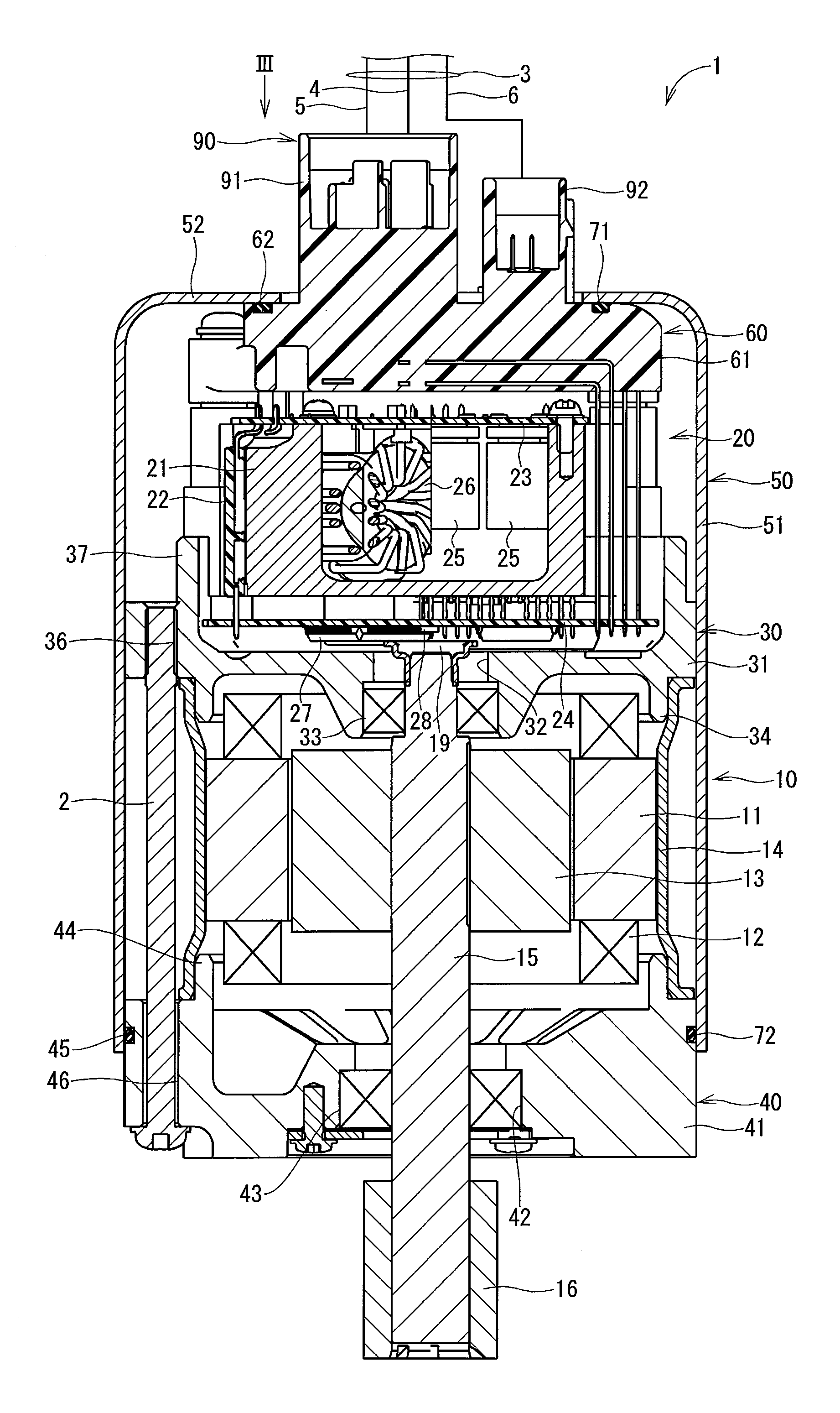
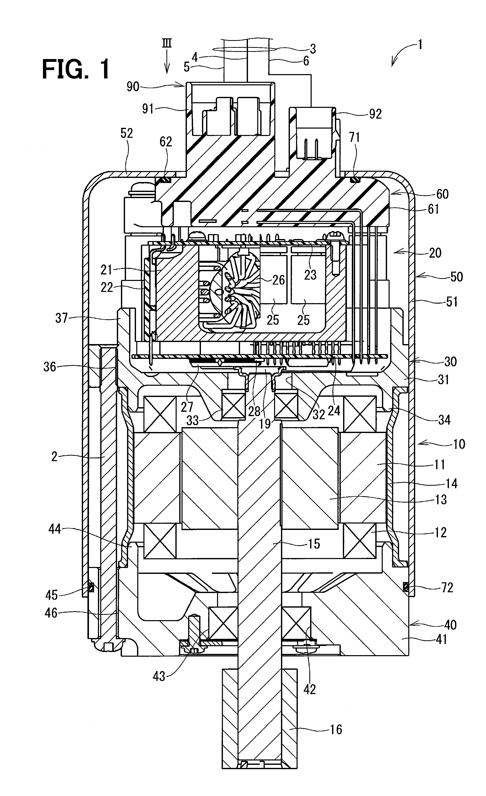
[0027]The rotating electric machine in the first embodiment of the present disclosure is shown in FIG. 1. The rotating electric machine 1 is driven by receiving an electric power supply, for example, and is used as an electric power steering device for assisting a steering operation of a vehicle.

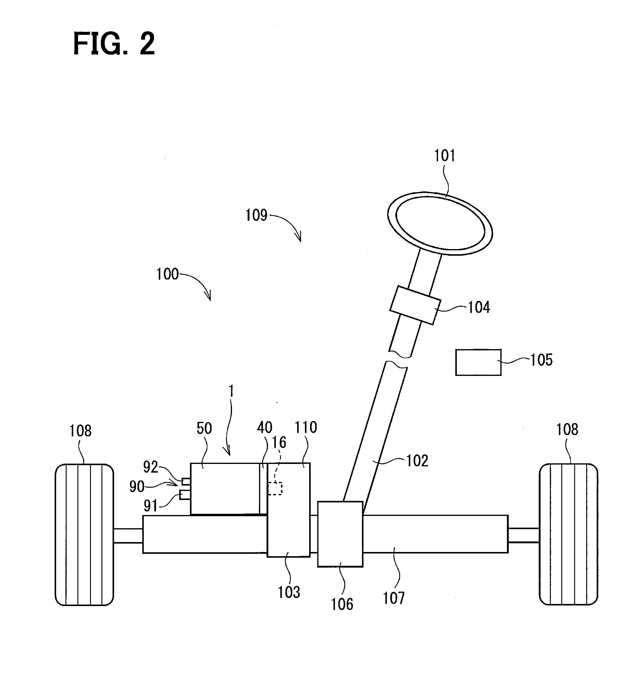
[0028]FIG. 2 shows an entire configuration of a steering system 100 having an electric power steering device 109. In the electric power steering device 109, a torque sensor 104 is disposed on a steering shaft 102 that is connected to a steering wheel 101. The torque sensor 104 detects a steering torque that is inputted to the steering shaft 102 via the steering wheel 101 from a driver.

[0029]A pinion gear 106 is disposed at a tip of the steering shaft 102, and the pinion gear 106 engages a rack shaft 107. On both ends of the rack shaft 107, a pair of tires 108 is steered via a tie rod.

[0030]In such configuration, when the driver rotates the steering wheel 101, the steering shaft 102 connected...

second embodiment

[0085]The rotating electric machine in the second embodiment of the present disclosure is shown in FIGS. 6-9.

[0086]In the second embodiment, a structure of the second frame and other part are different from the first embodiment.

[0087]As shown in FIG. 6, in the second embodiment, the frame body 41 of the second frame 40 has a concave part 47, instead of having the through hole 46 in the first embodiment. The concave part 47 is formed on one side of the frame body 41 which is close to the motor section 10 (i.e., on a motor section side surface of the second frame 40). Further, the bolt 2 is inserted into the through hole 36 of the first frame 30 and an end of the bolt is fastened in a screw-fastened state into the concave part 47 so that the first frame 30 and the second frame 40 are fastened. Here, one end (i.e., a head) of the bolt 2 is stopped on one side, i.e., the cylinder part 37 side, of the frame body 31, and the other end of the bolt 2 (i.e., an opposite end relative to the h...


PUM


Abstract

A rotating electric machine includes a motor section and a controller section. The motor section includes an annular stator, a winding wire wound on the stator, and a rotor rotatably disposed inside the stator. The controller section is positioned in an axially non-overlapping position with the stator and controls an electric power supply to the winding wire for a drive control of the motor section. The rotating electric machine also includes a cover having a cylindrical shape which seamlessly covers the controller section and the motor section. The rotating electric machine further includes a lid section for sealing of an end part of the cover. As a result, the rotating electric machine is sealed from dust and water.

Description

CROSS REFERENCE TO RELATED APPLICATION[0001]The present application is based on and claims the benefit of priority of Japanese Patent Application No. 2013-225289, filed on Oct. 30, 2013, the disclosure of which is incorporated herein by reference.TECHNICAL FIELD[0002]The present disclosure generally relates to a rotating electric machine having a seamless body that contains a motor section and a controller section.BACKGROUND INFORMATION[0003]Conventionally, a rotating electric machine includes a motor section and a controller section that controls the motor section. For example, in the rotating electric machine disclosed in a patent document 1 (i.e., Japanese Patent Laid-Open No. 2013-90376), the controller section is positioned in an area outside of the stator of the motor section in an axial direction. The positioning of the controller section outside of the stator in the axial direction may also be described as axially non-overlapping with the stator of the motor section along an...

Claims


Application Information

Patent Timeline
Patent Type & Authority Applications(United States)
IPC IPC(8): H02K5/10H02K5/22H02K11/00
CPCH02K5/10H02K5/225H02K11/0073H02K5/04H02K11/33
Inventor YAMASAKI, MASASHI
Owner DENSO CORP
Why Eureka
Try Eureka