
Ultrasound transducer and method for manufacturing an ultrasound transducer

a transducer and ultrasound technology, applied in the field of ultrasonic transducers and manufacturing methods of ultrasound transducers, can solve the problems of relative serious health problems, cardiac death, and the insufficient resolution of known ivus scanning devices for imaging some symptoms, and achieve the effect of higher acoustic impedance and higher acoustic impedan

Inactive Publication Date: 2015-04-30
GENERAL ELECTRIC CO
View PDF8 Cites 17 Cited by
  • Summary
  • Abstract
  • Description
  • Claims
  • Application Information

AI Technical Summary

Benefits of technology

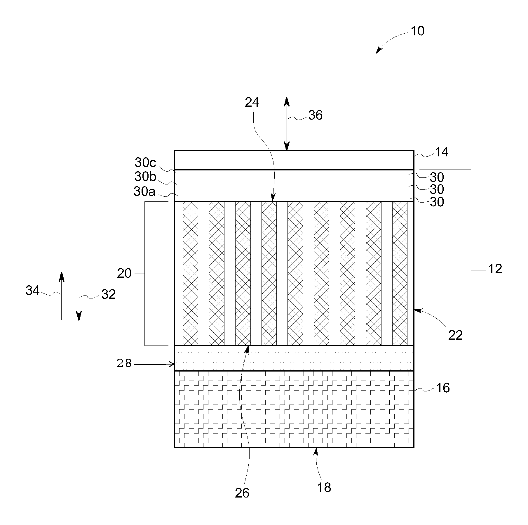
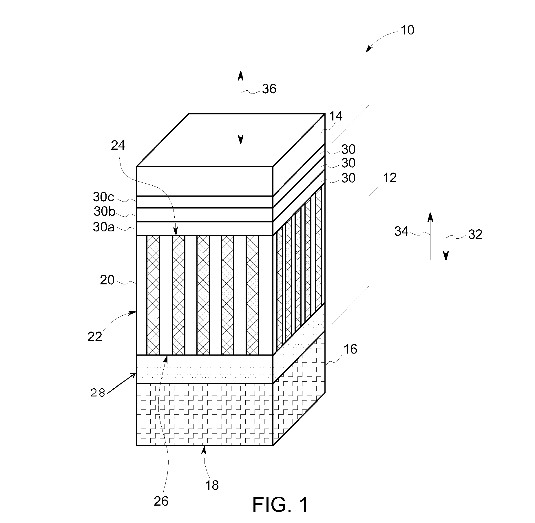
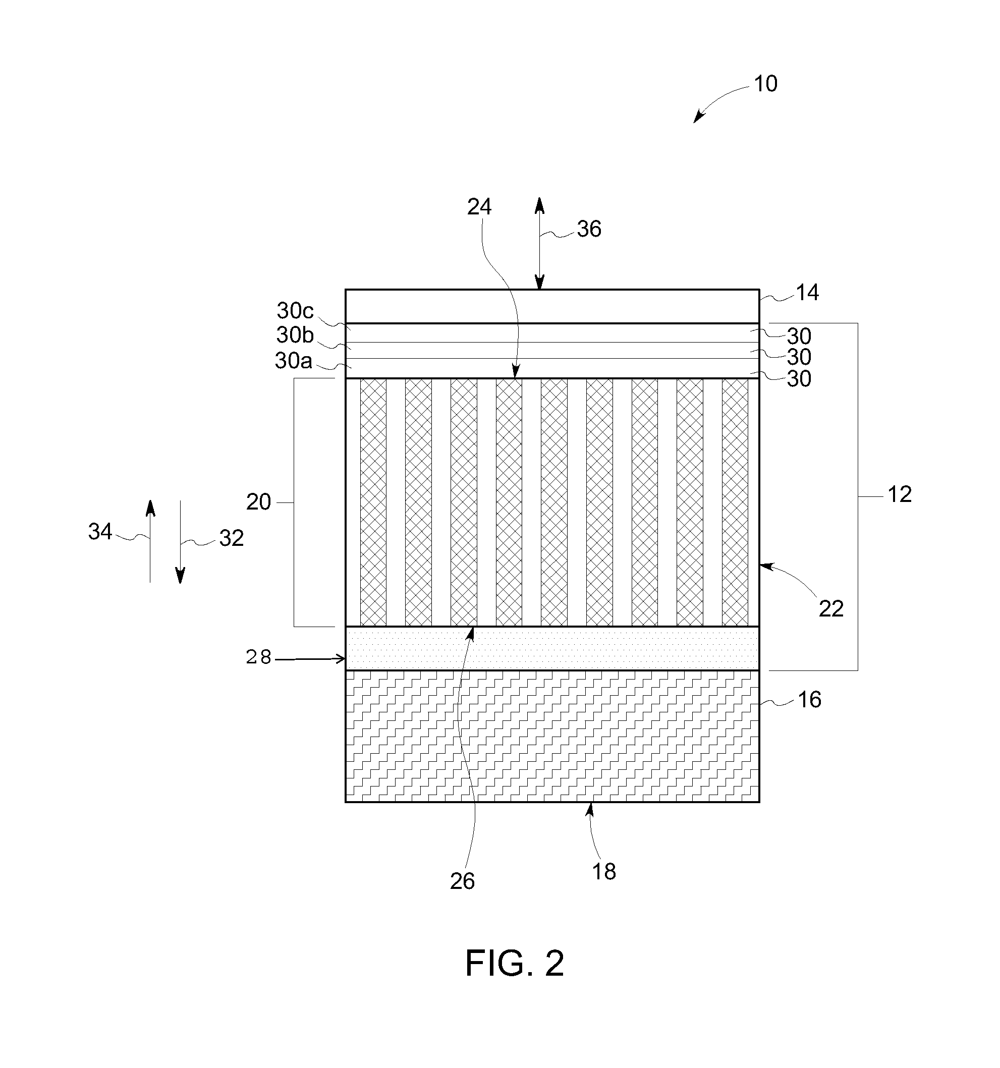
The patent text describes an ultrasound transducer with improved sensitivity and resolution. The transducer includes a micromachined piezoelectric composite body that converts electrical signals into ultrasound waves and back again. A dematching layer with higher acoustic impedance than the composite body is connected to the back side of the composite body, which helps to prevent signal loss and improve sensitivity. A lens is also connected to the front side of the composite body for better imaging quality. Overall, this design provides superior performance and reliability for ultrasound imaging applications.

Problems solved by technology

Progression of plaques can cause lumen narrowing and intracoronary thrombosis, which may lead to relatively serious health problems such as heart attack, stroke, or even cardiac death.
But, known IVUS scanning devices may have insufficient resolution for imaging some symptoms of atherosclerosis.
For example, the transducers of known IVUS scanning devices operate between approximately 20 and approximately 45 MHz in center frequency with a bandwidth between approximately 30% and approximately 50%, which may provide insufficient resolution for evaluating the vulnerability of plaques with relatively thin fiberous caps (e.g., less than approximately 64 μm).

Method used


Image

  • Ultrasound transducer and method for manufacturing an ultrasound transducer
  • Ultrasound transducer and method for manufacturing an ultrasound transducer
  • Ultrasound transducer and method for manufacturing an ultrasound transducer

Examples


Embodiment Construction

[0014]The foregoing summary, as well as the following detailed description of certain embodiments will be better understood when read in conjunction with the appended drawings. To the extent that the figures illustrate diagrams of the functional blocks of various embodiments, the functional blocks are not necessarily indicative of the division between hardware circuitry. Thus, for example, one or more of the functional blocks (e.g., processors or memories) may be implemented in a single piece of hardware (e.g., a general purpose signal processor or a block of random access memory, hard disk, or the like) or multiple pieces of hardware. Similarly, the programs may be stand alone programs, may be incorporated as subroutines in an operating system, may be functions in an installed software package, and / or the like. It should be understood that the various embodiments are not limited to the arrangements and instrumentality shown in the drawings.

[0015]As used herein, an element or step r...


PUM

PropertyMeasurementUnit
center frequencyaaaaaaaaaa
thicknessaaaaaaaaaa
thicknessaaaaaaaaaa

Abstract

An ultrasound transducer includes an acoustic layer that includes a micromachined piezoelectric composite body having a front side and an opposite back side. The micromachined piezoelectric composite body is configured to convert electrical signals into ultrasound waves to be transmitted from the front side toward a target. The micromachined piezoelectric composite body is configured to convert received ultrasound waves into electrical signals. A dematching layer is connected to the back side of the micromachined piezoelectric composite body of the acoustic layer. The dematching layer has a higher acoustic impedance than an acoustic impedance of the acoustic layer.

Description

BACKGROUND[0001]Atherosclerosis is a systemic disease in which fatty deposits, inflammation, cells, and scar tissue build up within the arterial wall. Progression of plaques can cause lumen narrowing and intracoronary thrombosis, which may lead to relatively serious health problems such as heart attack, stroke, or even cardiac death.[0002]Ultrasound imaging has become a valuable medical imaging modality for the diagnosis of atherosclerosis. Specifically, catheter and / or guide wire based intravascular ultrasound (IVUS) imaging techniques have been used to facilitate atherosclerosis diagnoses. But, known IVUS scanning devices may have insufficient resolution for imaging some symptoms of atherosclerosis. For example, the transducers of known IVUS scanning devices operate between approximately 20 and approximately 45 MHz in center frequency with a bandwidth between approximately 30% and approximately 50%, which may provide insufficient resolution for evaluating the vulnerability of plaq...

Claims


Application Information

Patent Timeline
Patent Type & Authority Applications(United States)
IPC IPC(8): H01L41/09H01L41/22
CPCH01L41/22H01L41/09A61B8/12A61B8/4405A61B8/4427A61B8/4444A61B8/4483A61B8/465B06B1/0677Y10T29/42
Inventor LI, XIANGFAN, YING
Owner GENERAL ELECTRIC CO
Learn More