

Input circuit
a technology of input circuits and inputs, applied in the field of input circuits, to achieve the effect of high accuracy and avoiding inflammation
- Summary
- Abstract
- Description
- Claims
- Application Information
AI Technical Summary
Benefits of technology
Problems solved by technology
Method used
Image

Examples
embodiment example 1
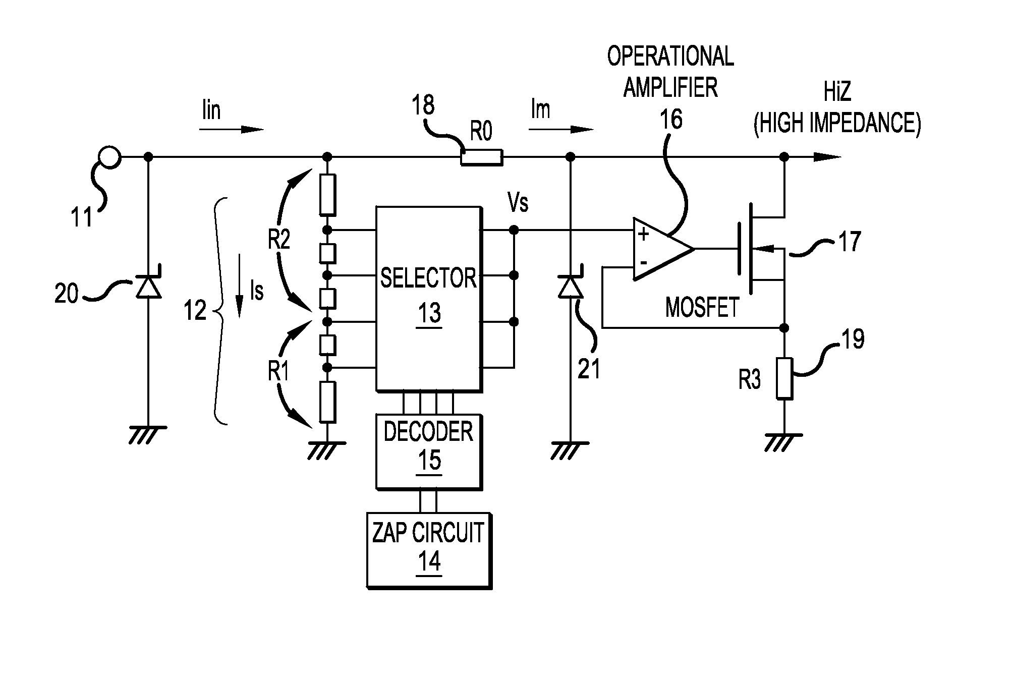
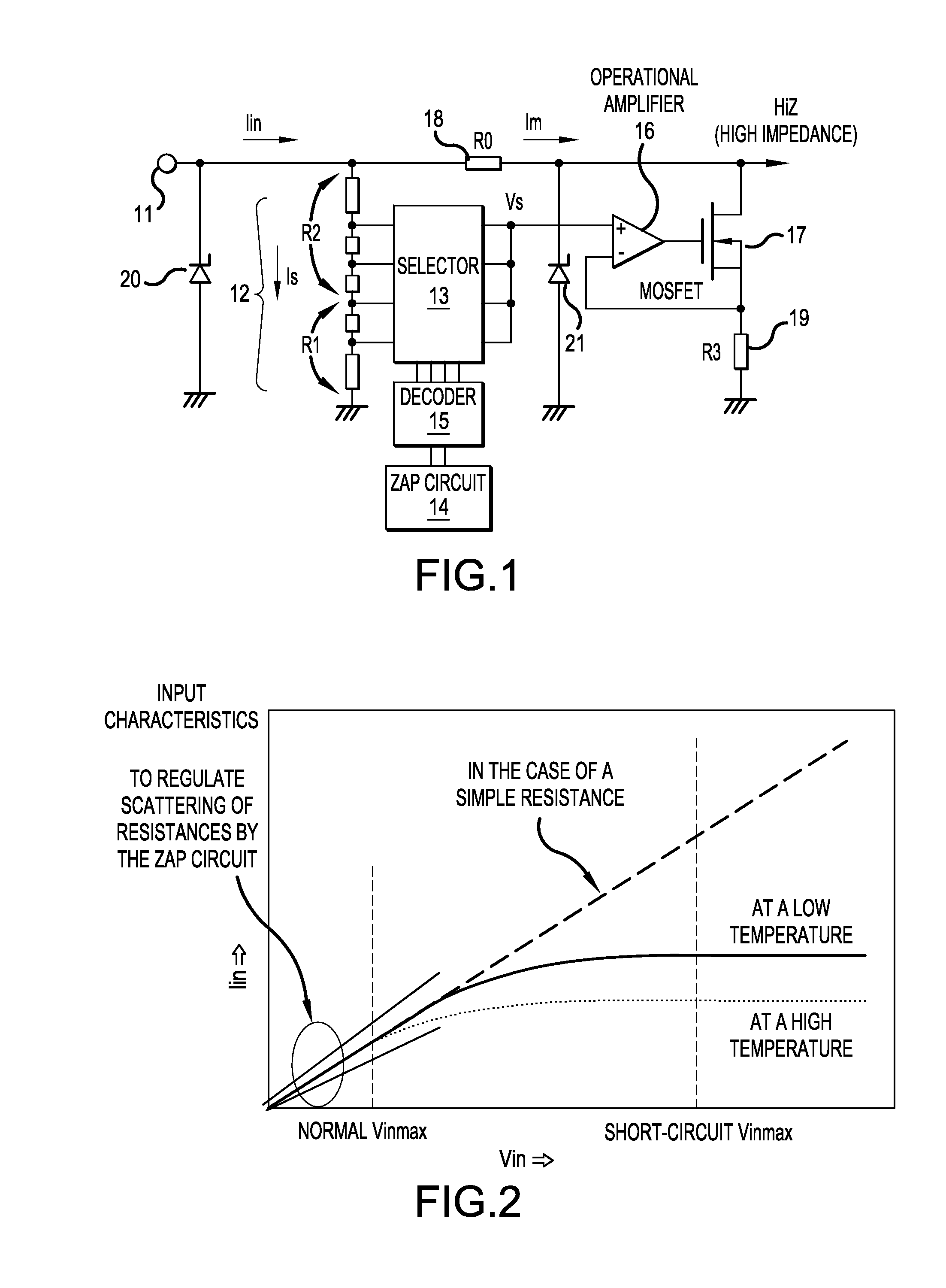
[0023]FIG. 1 shows a construction of an input circuit according to Embodiment Example 1 of the invention. Referring to FIG. 1, a dividing resistor 12 is connected to an input terminal 11. Some of the nodes in the dividing resistor 12 are connected to a selector 13 composed of a row of analog switches. A zap circuit 14 and a decoder 15 that decodes the output from the zap circuit 14 turn ON only one of the analog switches in the selector 13, which in turn delivers an electric potential Vs at the node of the dividing resistor selected by the zap circuit 14.
[0024]In place of the construction described above, an output from the zap circuit 14 can be directly delivered to the selector 13, although such a construction may exhibits a degraded efficiency in the case of a large number of selections. The zap circuit 14 can be replaced by an electrically erasable programmable read-only memory (EEPROM). Because the dividing resistor 12 can be set at a relatively high resistance value, a part of...
embodiment example 2
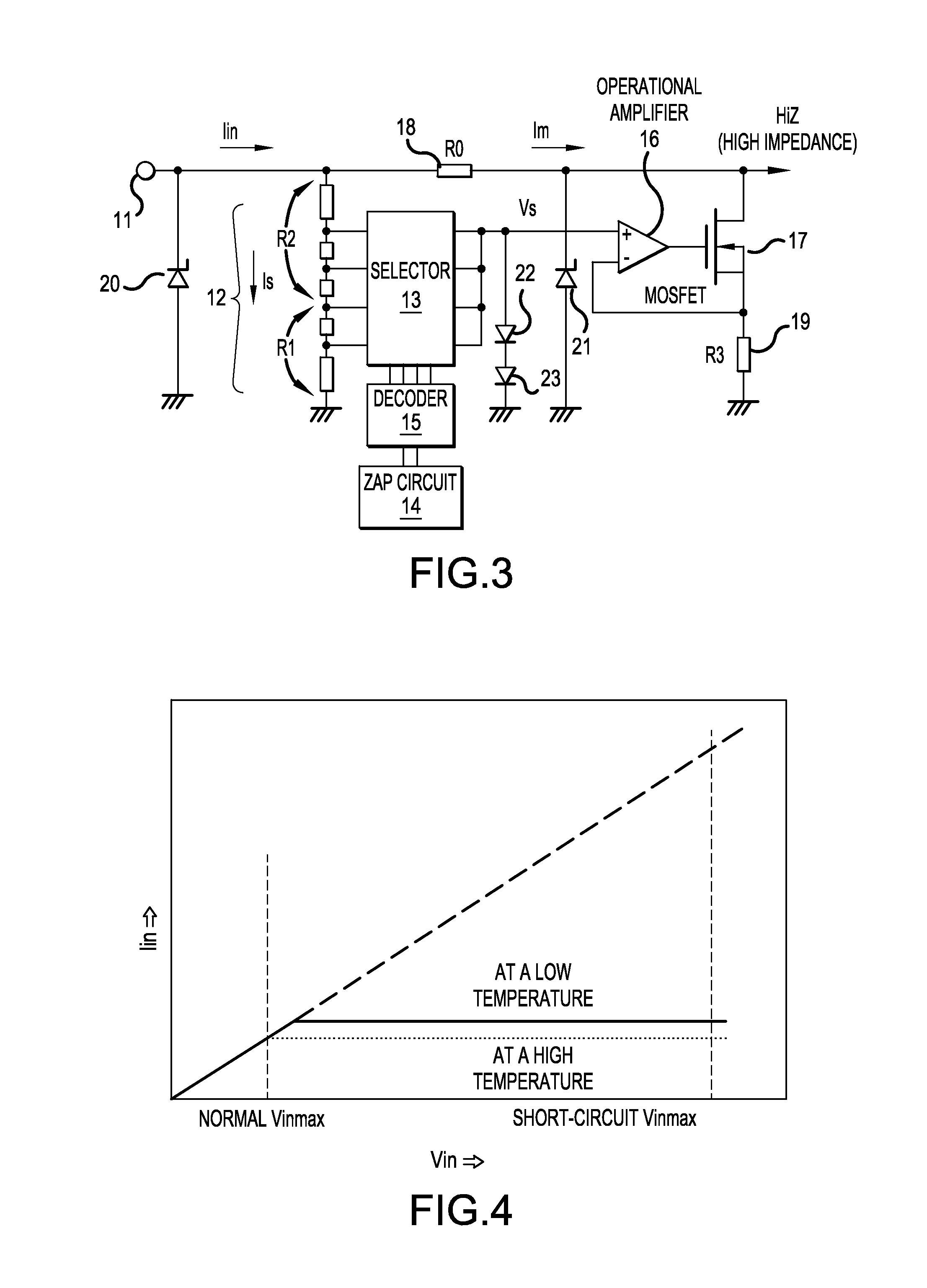
[0035]FIG. 3 shows a construction of an input circuit according to Embodiment Example 2 of the present invention. This circuit differs from the input circuit according to Embodiment Example 1 shown in FIG. 1 in that clamping diodes 22 and 23 are connected between the output of the selector 13 and the base potential, the ground potential. The clamping diodes 22 and 23 clamp the output voltage Vs of the selector 13 at a forward voltage (or a drift voltage) of the diodes. Even if an input voltage higher than the clamping voltage is applied, the current is controlled within the value corresponding to the clamping voltage. The number of clamping diodes is determined corresponding to the necessary clamping voltage.
[0036]FIG. 4 shows a relationship between input voltage Vin and input current Iin in the input circuit according to Embodiment Example 2 of the present invention. The current is controlled at a certain constant value for input voltages higher than a specified value. In Embodimen...
embodiment example 3
[0038]FIG. 5 shows a construction of an input circuit according to Embodiment Example 3 of the present invention. This input circuit differs from the input circuit according to Embodiment Example 2 as shown in FIG. 3 in that the output voltage Vs of the selector 13 is connected through a reverse current preventing diode 24 to the output terminal of a voltage follower 25, and the input of the voltage follower 25 is connected through a temperature dependence compensating diode 26 to a voltage source 27. A resistance 28 is provided to establish a forward voltage (a drift voltage) of the temperature dependence compensating diode 26 by supplying a feeble current through the temperature dependence compensating diode 26.
[0039]The reverse current preventing diode 24 is provided for preventing the output Vs of the selector 13 from rising when the electric potential of the reference power supply is higher than the input voltage Vin in the relatively low voltage region of the input voltage. Be...
PUM
 Abstract
Description
Claims
Application Information