Radiation measurement system and method with synchronous high speed tracking laser based position measurement

a technology of laser based position measurement and radiation measurement system, which is applied in the direction of measurement devices, antenna radiation diagrams, instruments, etc., can solve the problems of high cost of measurement system, large errors, and still be expected errors, and achieve high performance

Active Publication Date: 2015-04-30
M I TECH
View PDF9 Cites 33 Cited by
  • Summary
  • Abstract
  • Description
  • Claims
  • Application Information

AI Technical Summary

Benefits of technology

[0010]Thus, one advantage of the present invention is that calibration prior to or intermittent to the collection of RF measurements is not necessary to obtain precise near-field...

Problems solved by technology

The near-field measurements must be extremely precise because small errors in the near-field measurements translate into large errors when the near-field data is transformed into far-field data.
Thus, any variance in the actual position of the probe and each of the plurality of discrete measurement points will result in significant errors when the near-field data is transformed into far-field data.
The problem with this approach is that such measurements systems are extremely costly, and still some error can still be expected.
The problem with prior art systems such as this is that the proce...

Method used


Image

  • Radiation measurement system and method with synchronous high speed tracking laser based position measurement
  • Radiation measurement system and method with synchronous high speed tracking laser based position measurement
  • Radiation measurement system and method with synchronous high speed tracking laser based position measurement

Examples


Embodiment Construction

[0019]It is to be understood that both the foregoing general description and the following detailed description are exemplary. The descriptions herein are not intended to limit the scope of the present invention. The scope of the present invention is governed by the scope of the appended claims.

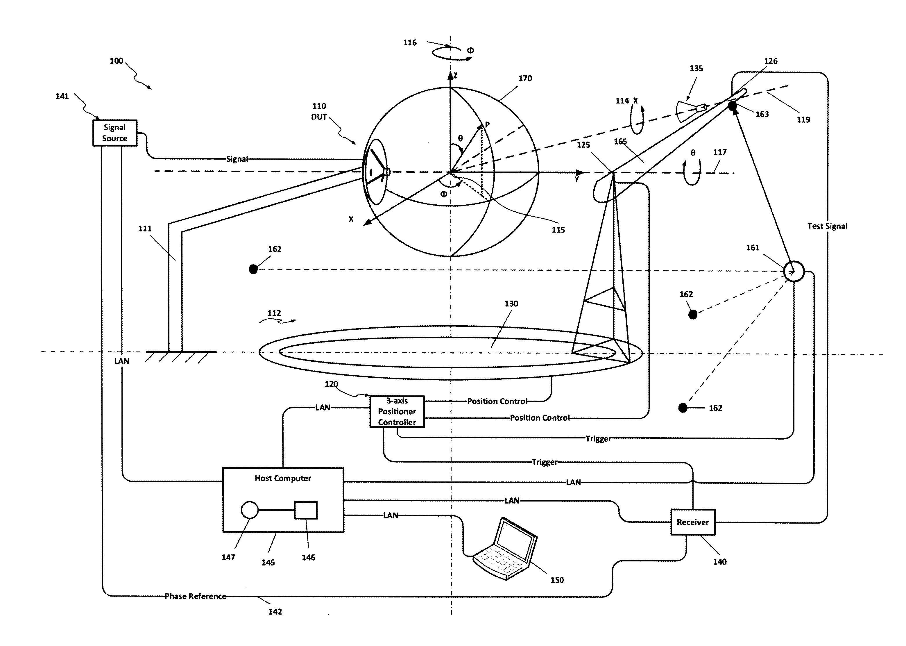
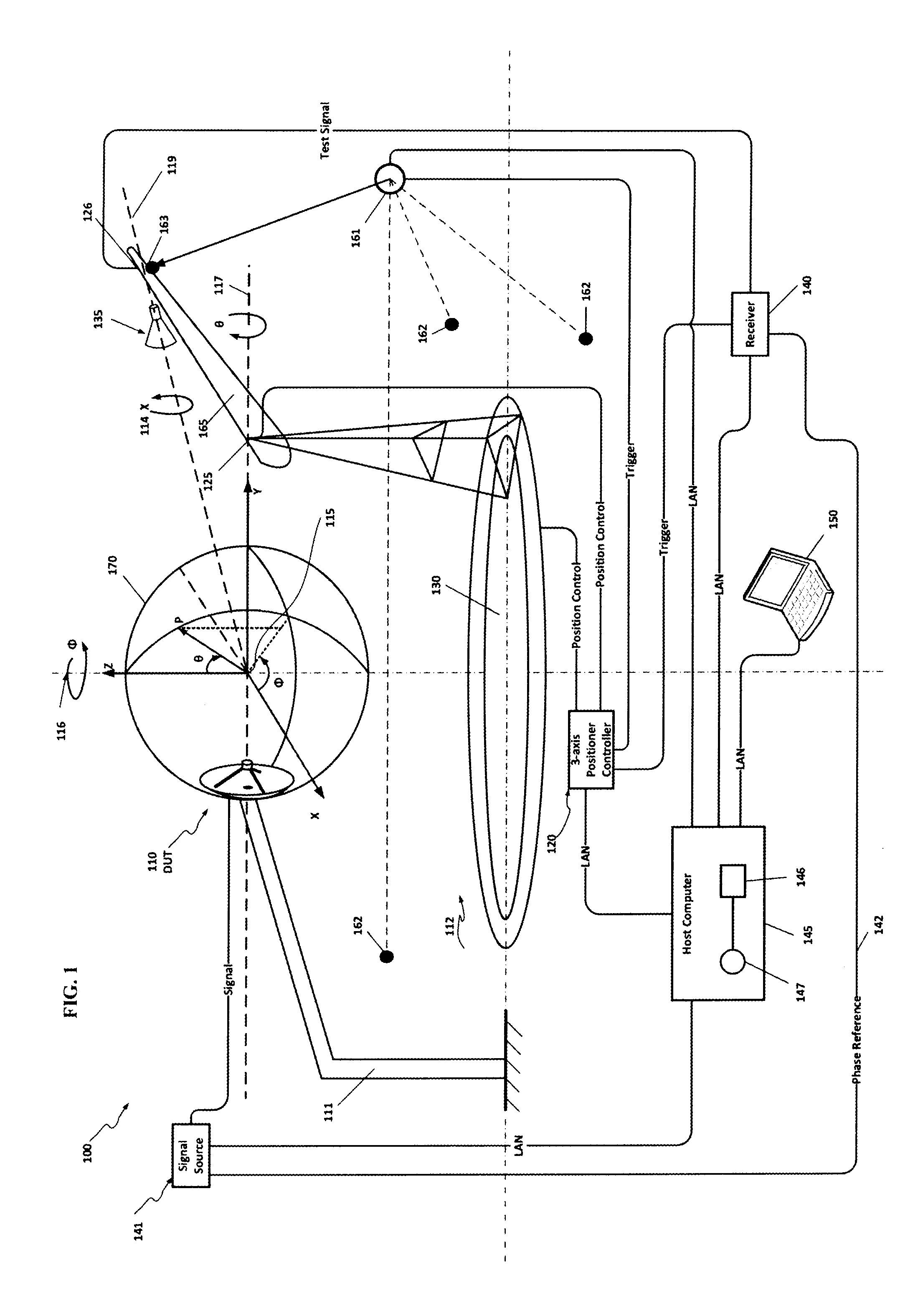
[0020]FIG. 1. illustrates a near-field measurement system 100, which also computes device far-field radiation patterns according to an exemplary embodiment of the present invention. System 100 includes a device under test (DUT) 110, which may be an antenna mounted to a support structure 111. DUT 110 may be connected to a signal source 141.

[0021]DUT 110 may be mounted to a support structure 111, near a three-axis positioner 112, which controls the orientation of a probe 135 aligned to a coordinate system having an origin 115 defined by the crossing of a phi axis 116 and a theta axis 117. This coordinate system is referred to herein as the global position coordinate system and it is defined by ...


PUM


Abstract

An Antenna measurement system incorporating high speed tracking laser-based global positioning capture synchronized with radio frequency (RF) measurements. A high speed tracking laser is used for collecting RF probe position data synchronously with corresponding near-field RF measurements. The probe may be moved across an arbitrary surface surrounding or adjacent to a device under test (DUT); however, it is not necessary for the probe position to be perfectly coincident with the surface, or any of the discrete points which make up the surface. Here, the probe position is determined relative to a global positioning coordinate system which is defined by a set of monuments which are in known positions relative to the global positioning coordinate system, and not the DUT. Any difference between the actual position of the probe, in the global position coordinate system, and a given one of the discrete measuring points, in the global position coordinate system, on the surface surrounding or adjacent to the DUT can be accounted for during post processing, thus eliminating the need for advanced or intermittent calibration to achieve precise near-field measurements.

Description

[0001]This application claims priority to U.S. Provisional Application No. 61 / 897,143, filed Oct. 29, 2013, the contents of which are incorporated herein by reference in its entirety.FIELD OF THE INVENTION[0002]The present invention relates to high accuracy radiation measurement systems, and more particularly, to an antenna measurement system that incorporates high speed tracking laser-based global positioning capture synchronized with radio frequency (RF) measurements.BACKGROUND[0003]Sophisticated high performance antennas are commonly used in both commercial and military applications. With respect to commercial applications, high performance antennas are used, for example, to support high speed voice, data, and video communications. In military applications, high performance antennas are, for example, used in conjunction with satellite communications; unmanned aerial vehicles; and various aircraft, ship and ground vehicle missions.[0004]Equally sophisticated antenna measurement sy...

Claims


Application Information

Patent Timeline
IPC IPC(8): G01R29/10G01R1/07G01R31/00
CPCG01R29/10G01R1/07G01R31/00G01R31/001
Inventor MANNION, MARTINPINSON, CHARLES P.B.FORDHAM, JEFFREYBAGGETT, MARION
Owner M I TECH
Why Eureka
Try Eureka