Sheet processing device and image forming device provided with the sheet processing device

Active Publication Date: 2015-04-30
NISCA KK
View PDF4 Cites 5 Cited by
  • Summary
  • Abstract
  • Description
  • Claims
  • Application Information

AI Technical Summary

Benefits of technology

[0028]Thus, according to the present invention, there can be provided a sheet processing device that performs saddle stitching processing that binds a bundle of stacked paper sheets at a position around a center thereof and then folds in half the paper sheet bundle at the binding portion, the device being capable of selecti

Problems solved by technology

However, in this configuration, a metallic staple cannot be used for saddle stitching of the paper sheets.
In general, the binding processing not using the metallic staple takes much time for the binding.
That is, it is impossible for one device to realize both the binding method using the metallic staple and that not usin

Method used


Image

  • Sheet processing device and image forming device provided with the sheet processing device
  • Sheet processing device and image forming device provided with the sheet processing device
  • Sheet processing device and image forming device provided with the sheet processing device

Examples


second embodiment

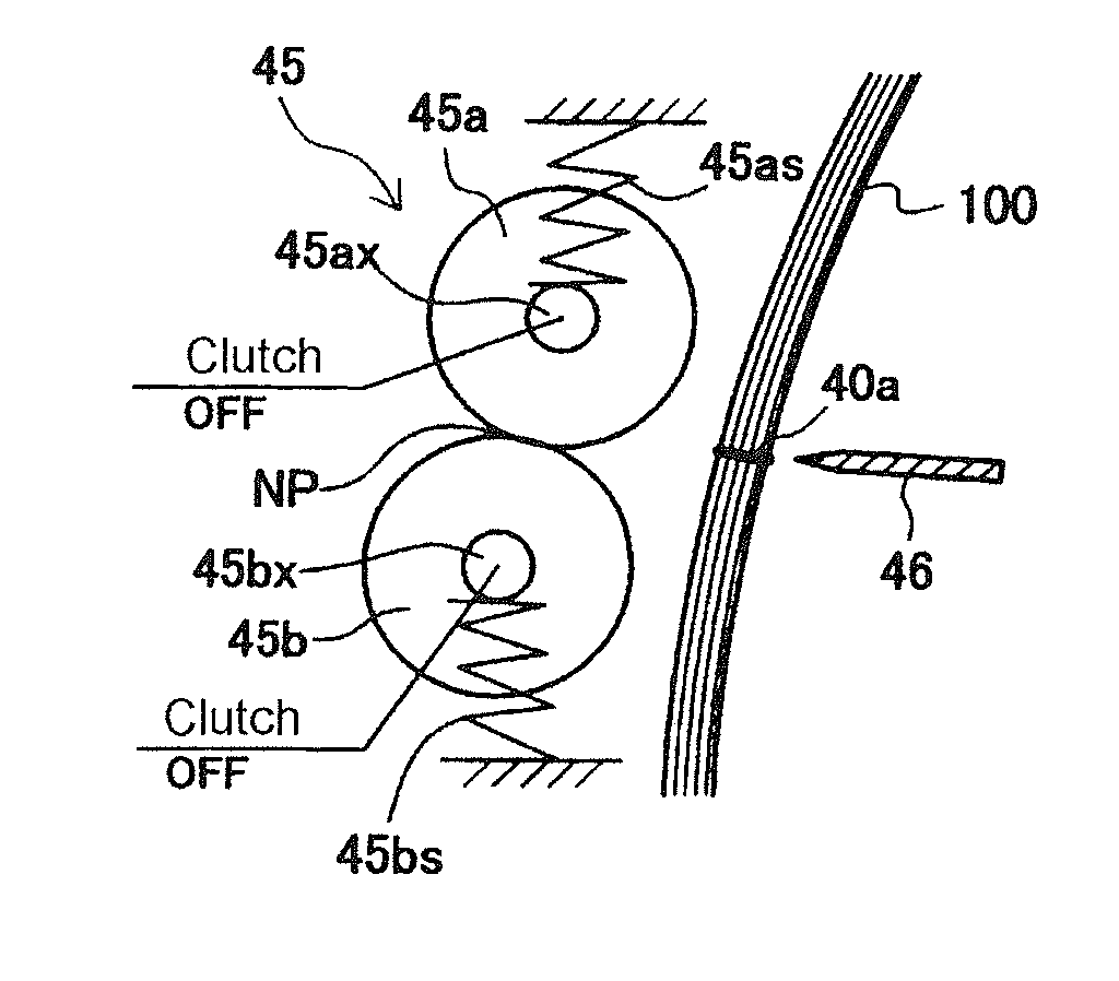
[0114]As illustrated in FIG. 12, in a second embodiment, the left and right saddle stitching staplers 40 for metallic staple illustrated in FIGS. 3A and 3B are disposed on the upstream side of the folding roller 45 and folding blade 46, and left and right saddle stitching staplers 50 for paper-made staple illustrated in FIG. 6 are disposed on the downstream side of the folding roller 45 and folding blade 46. With this configuration, both the saddle stitching staplers 50 for paper-made staple and saddle stitching staplers 40 for metallic staple can be disposed closer to the folding roller 45 and folding blade 46 than in the case where the stapler 50 and stapler 40 are continuously installed on one side of the folding roller 45 and folding blade 46. Further, by disposing the stapler 50 and stapler 40 on both sides of the folding roller 45 and folding blade 46, respectively, it is possible to effectively use a space of the stacker section 35. Further, by disposing the saddle stitching ...

third embodiment

[0115]As illustrated in FIG. 13, in a third embodiment, the left and right saddle stitching staplers 50 for paper-made staple illustrated in FIG. 6 are disposed on the upstream side of the folding roller 45 and folding blade 46, and left and right saddle stitching staplers 40 for metallic staple illustrated in FIGS. 3A and 3B are disposed on the downstream side of the folding roller 45 and folding blade 46. With this configuration, the same effects as those in the second embodiment can be obtained. Further, in the third embodiment, the saddle stitching staplers 40 for metallic staple are disposed on the downstream side of the folding roller 45 and folding blade 46, so that even if the metallic staple 40a drops due to blank drive of the stapler, it does not go into the saddle stitching stapler 50 for paper-made staple or folding roller 45 side. The stop positions of the stopper 38 for stopping the paper sheet bundle 100 are as illustrated in FIG. 13.

fourth embodiment

[0116]As illustrated in FIG. 14, in a fourth embodiment, the left and right saddle stitching staplers 40 for metallic staple illustrated in FIGS. 3A and 3B and left and right saddle stitching staplers 50 for paper-made staple illustrated in FIG. 6 are disposed on the downstream side of the folding roller 45 and folding blade 46. Further, the saddle stitching staplers 50 for paper-made staple are disposed closer to the folding roller 45 and folding blade than the saddle stitching staplers 40 for metallic staple. Also with this configuration, it is possible to suppress the paper-made staple 60 with a low tolerance to resistance from coming off from the paper sheet bundle 100. Further, the saddle stitching staplers 40 for metallic staple are disposed on the downstream side of the folding roller 45 and folding blade 46, so that even if the metallic staple 40a drops due to blank drive of the stapler, it does not go into the saddle stitching stapler 50 for paper-made staple or folding rol...


PUM

PropertyMeasurementUnit
Sizeaaaaaaaaaa

Abstract

To provide a sheet processing device that performs saddle stitching processing that binds a bundle of stacked paper sheets at a position around a center thereof and then folds in half the paper sheet bundle at the binding portion, the device being capable of selectively performing both saddle stitching using a metallic staple and saddle stitching not using the metallic staple for environmental protection and capable of reducing a size.
A sheet processing device includes a stacker section that temporarily stacks conveyed paper sheets in a substantially vertical attitude, a stopper that regulates the paper sheets stacked in the stacker section, a first binding section that is provided in the stacker and saddle-stitches, with a metallic staple, a paper sheet bundle at a binding position around a center of the paper sheet bundle in a sheet conveying direction, a second binding section that saddle-stitches, without using the metallic staple, the paper sheet bundle at the binding position around the center of the paper sheet bundle in the sheet conveying direction, and a folding section that folds in half the paper sheet bundle. An interval between the second binding section and folding section is set smaller than an interval between the first binding section and folding section.

Description

BACKGROUND OF THE INVENTION[0001]1. Field of the Invention[0002]The present invention relates to a sheet processing device that binds paper sheets carried out from an image forming device such as a copier or a printer and folds the bound paper sheets at a predetermined folding position and, more particularly, to a sheet processing device capable of performing binding processing suitable for intended use when binding a paper sheet bundle at a portion around a center thereof and then folding the bound paper sheet bundle.[0003]2. Description of the Related Art[0004]There are widely known processing devices that fold a paper sheets carried out from an image forming device in a booklet form. These processing devices are provided with a sheet stacking means for sheet processing. In the sheet stacking means, the paper sheets are stacked in a bundle and are then saddle stitched and folded in a booklet form. Further, in recent years, a binding device that binds a paper sheet bundle without u...

Claims


Application Information

Patent Timeline
IPC IPC(8): B42B2/02
CPCB42B2/02B26F1/02B42B4/00B42C1/12B42C19/02B65H31/02B65H37/04B65H45/18B65H2301/42146B65H2701/18292B65H2801/27G03G15/6541G03G15/6582B31F5/00B31F5/06B42F3/003B65H5/06B65H5/08B65H31/00B65H35/04B65H37/06B65H2301/43826B65H2301/4505B65H2801/48G03G15/00
Inventor KUBOTA, KAZUYUKIFUKASAWA, EIJIKUBOTA, ICHITAROKUBOTA, HIDEYUKIOSADA, HISASHINAKANO, TAKAHIROSORITA, HIROYUKINAKAJIMA, JUNYAKOBAYASHI, TAKUMAKUBOTA, YUUKISAITO, TAKASHIKONDO, ISAO
Owner NISCA KK
Why Eureka
Try Eureka