Ultrasonic imaging apparatus and a method for imaging a specular object and a target anatomy in a tissue using ultrasond

a technology of ultrasonic imaging and target anatomy, which is applied in the field of ultrasonic imaging apparatus and a method for imaging specular objects and target anatomy in tissue using ultrasond, can solve the problems of other imaging alternatives, such as xray or em (electromagnetic) guidance, suffer from drawbacks, and only have a 2d view, and achieves high frame rate. , the effect of high frame ra

Active Publication Date: 2015-04-30
KONINKLIJKE PHILIPS ELECTRONICS NV
View PDF9 Cites 2 Cited by
  • Summary
  • Abstract
  • Description
  • Claims
  • Application Information

AI Technical Summary

Benefits of technology

[0023]It is noted that international patent application WO 2008 / 126015 describes an ultrasonic diagnostic imaging system that scans a plurality of planar slices in a volumetric region which are parallel to each other. The image data of the individual slices is combined by projecting the data in the elevation dimension to produce a so-called “thick slice” image. The thick slice image is then displayed at a high frame rate by combining a single newly acquired slice with slices previously acquired. The described method thus aims at providing, in the tissue imaging step, spatially compounded images which can be generated at a high frame rate.

Problems solved by technology

Other imaging alternatives, such as Xray or EM (electromagnetic) guidance, suffer from drawbacks such as risk of radiation exposure, 2D view only, additional set-up time, tracking errors or lack of visibility of the specular object, such as a biopsy needle.
However, in a significant number of cases the needle location deviates from the target plane due to, for example, tissue heterogeneities and bevel asymmetry.
It is now a problem of the known method that such an out-of-plane needle is not shown (or not sufficiently shown) in the combined (needle-enhanced) images.
Furthermore, since the clinician does not know where the needle is located in relation to the original target plane, he has no indication how to move the transducer to find the needle.

Method used


Image

  • Ultrasonic imaging apparatus and a method for imaging a specular object and a target anatomy in a tissue using ultrasond
  • Ultrasonic imaging apparatus and a method for imaging a specular object and a target anatomy in a tissue using ultrasond
  • Ultrasonic imaging apparatus and a method for imaging a specular object and a target anatomy in a tissue using ultrasond

Examples


Embodiment Construction

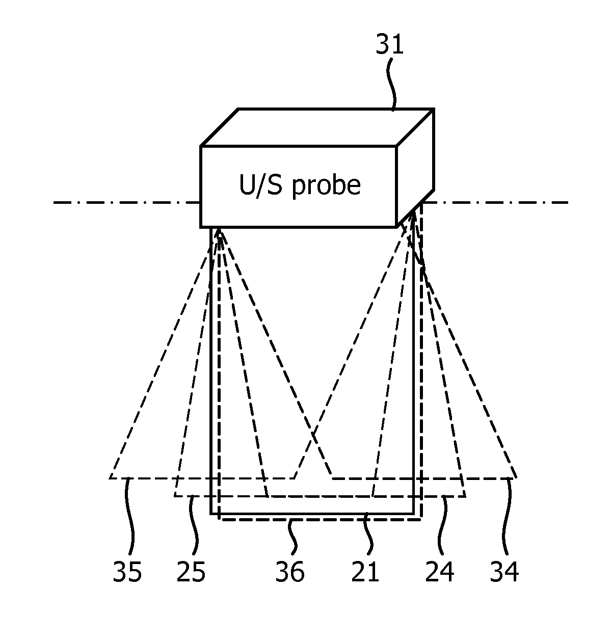
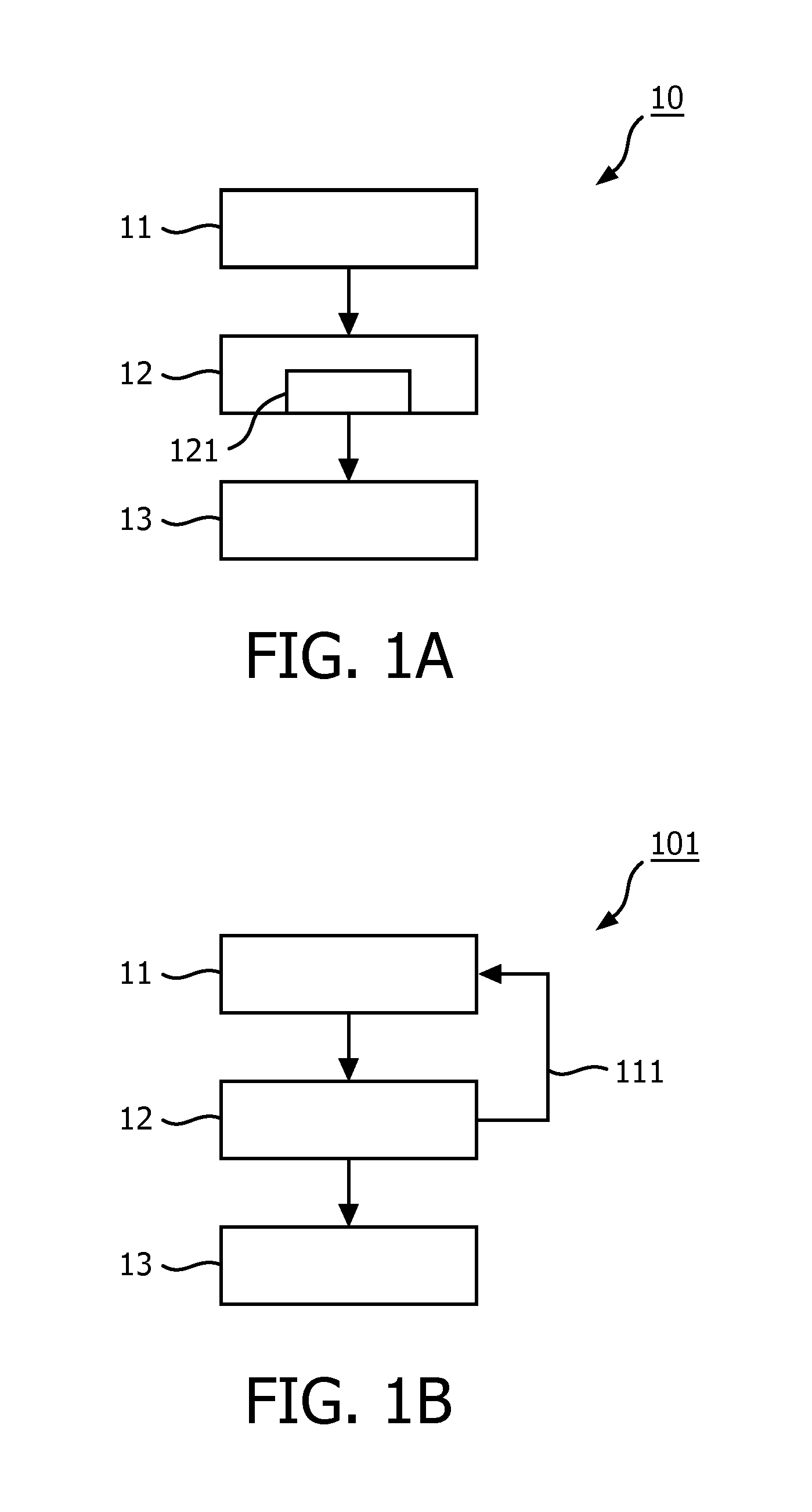
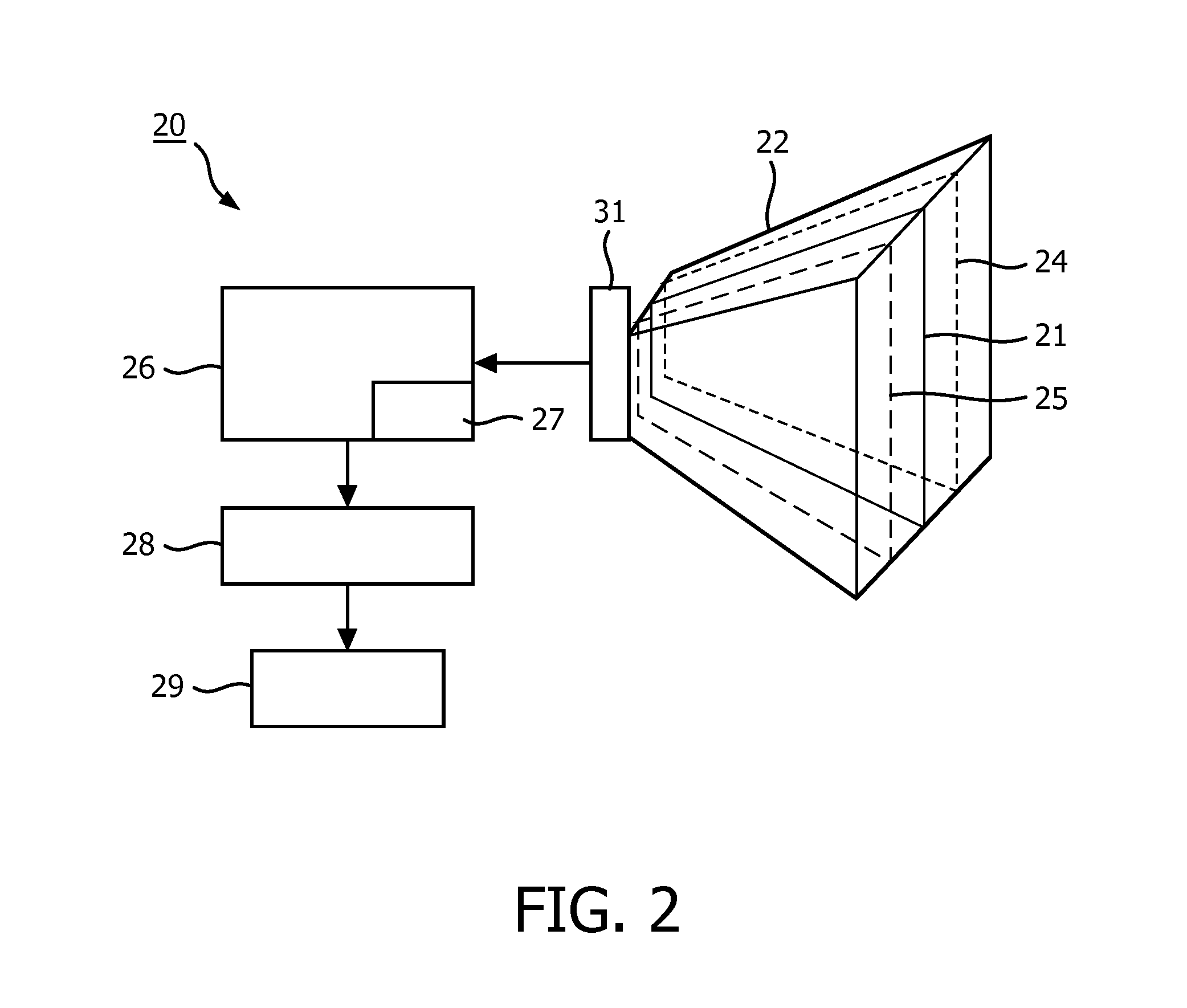
[0028]FIG. 1A illustrates an embodiment 10 of the method according to the invention. The embodiment 10 comprises a tissue imaging step 11 of transmitting first sound waves into a volumetric region 22, of receiving echoes of said first sound waves from a target plane 21 (said target plane including the target anatomy), and of processing said received echoes to produce a tissue image. In this tissue imaging step 11a tissue mode specific set of parameters is used, thereby ensuring the optimal imaging of the target anatomy in the tissue. The embodiment 10 further comprises a specular object imaging step 12 of transmitting second sound waves into said volumetric region 22, of receiving echoes of said second sound waves from a plurality of image planes 24, 25 separated in an elevation direction at selected elevations around the target plane 21, and of processing the echoes received from the target plane and from the plurality of image planes to produce a specular object image. In this spe...


PUM


Abstract

The invention relates to a method and an ultrasonic imaging apparatus (20) for imaging a specular object (such as a biopsy needle) and a target anatomy in a tissue, whereby the specular object remains visible even when its location deviates from a target plane (21) including the target anatomy.

Description

FIELD OF THE INVENTION[0001]The invention relates to a method of imaging a specular object, such as for example a needle-like instrument, and a target anatomy in a tissue using ultrasound, the method comprising a tissue imaging step of transmitting first sound waves into a volumetric region of the tissue, the volumetric region including the target anatomy located in a target plane, of receiving echoes of said first sound waves from the target plane, and of processing said received echoes to produce a tissue image, said tissue imaging step using a tissue mode specific set of parameters, and a specular object imaging step of transmitting second sound waves into said volumetric region of the tissue, the volumetric region including the specular object, of receiving echoes of said second sound waves from the target plane, and of processing said received echoes to produce a specular object image, said specular object imaging step using a specular object mode specific set of parameters, an...

Claims


Application Information

Patent Timeline
Patent Type & Authority Applications(United States)
IPC IPC(8): A61B8/08A61B8/00A61B8/14G09G5/38G06T7/00
CPCA61B8/0841G09G5/38G06T7/0079A61B8/14G06T2207/30004A61B8/463G09G2340/12G06T2207/10132A61B8/483A61B8/4416A61B8/466A61B8/523A61B8/5246A61B2034/2063A61B2090/378
Inventor VIGNON, FRANCOIS GUY GERARD MARIECHANG, JINDANIELS, ALLISON ARDENJAIN, AMEET KUMAR
Owner KONINKLIJKE PHILIPS ELECTRONICS NV
Why Eureka
Try Eureka