

Magnetization controlling element using magnetoelectric effect
- Summary
- Abstract
- Description
- Claims
- Application Information
AI Technical Summary
Benefits of technology
Problems solved by technology
Method used
Image

Examples
first embodiment
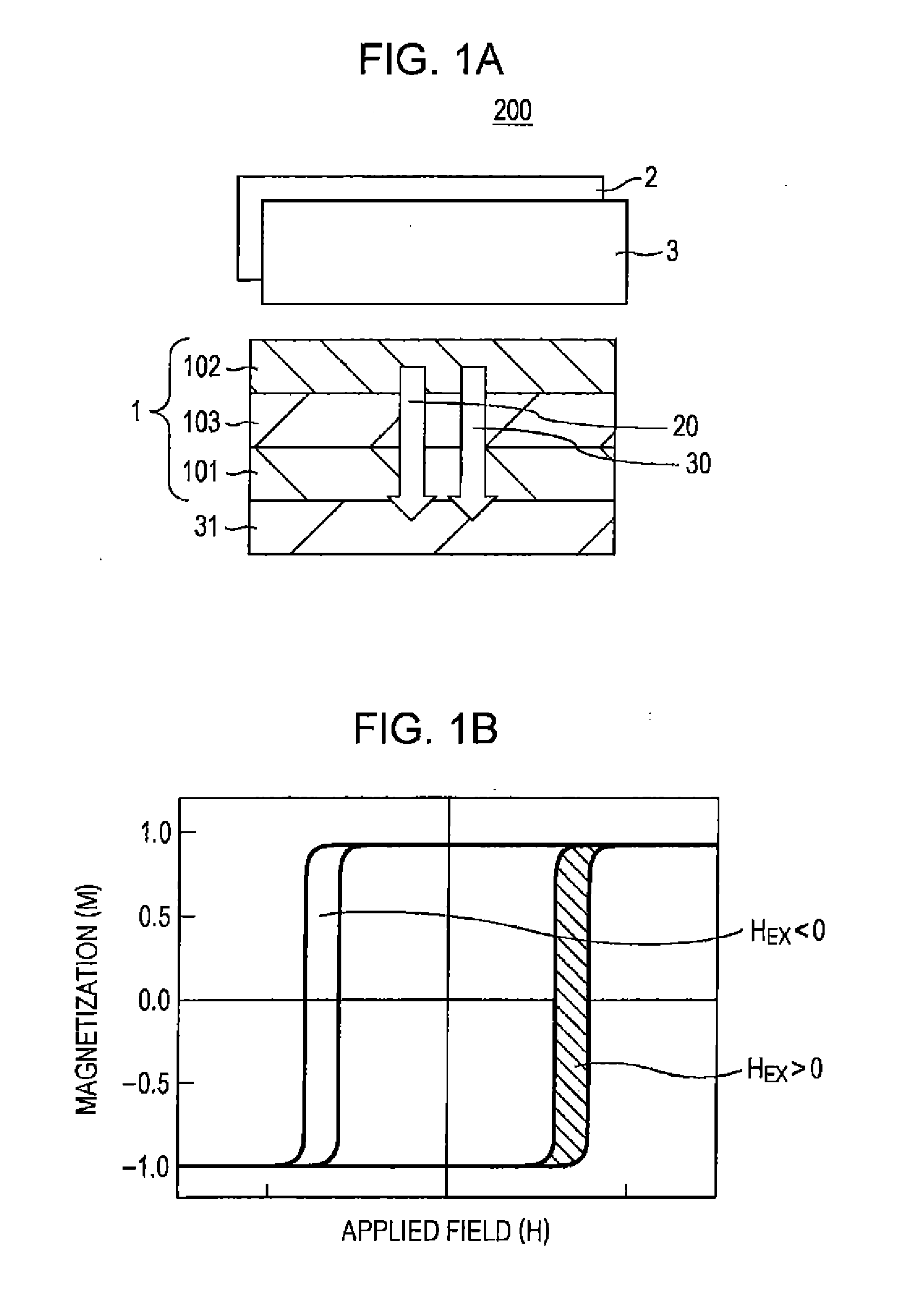
[0019]In a first embodiment, a magnetization controlling element disclosed in the present invention will be described. FIG. 1A schematically shows a magnetization controlling element disclosed in the present invention. The “magnetization controlling element” is defined as an element capable of controlling the magnetization direction by means of an external field and retaining (recording) the state even after the external field is removed. A magnetization controlling element 200 includes at least three components: an ME recording layer 1 which changes magnetization using the ME effect and retains that state, a magnetic field applying mechanism 2 which applies a magnetic field to the ME recording layer 1, and an electric field applying mechanism 3 which applies an electric field to the ME recording layer 1. The arrows 20 and 30 in FIG. 1A indicate a magnetic field and an electric field applied from the magnetic field applying mechanism 2 and the electric field applying mechanism 3. As...
second embodiment
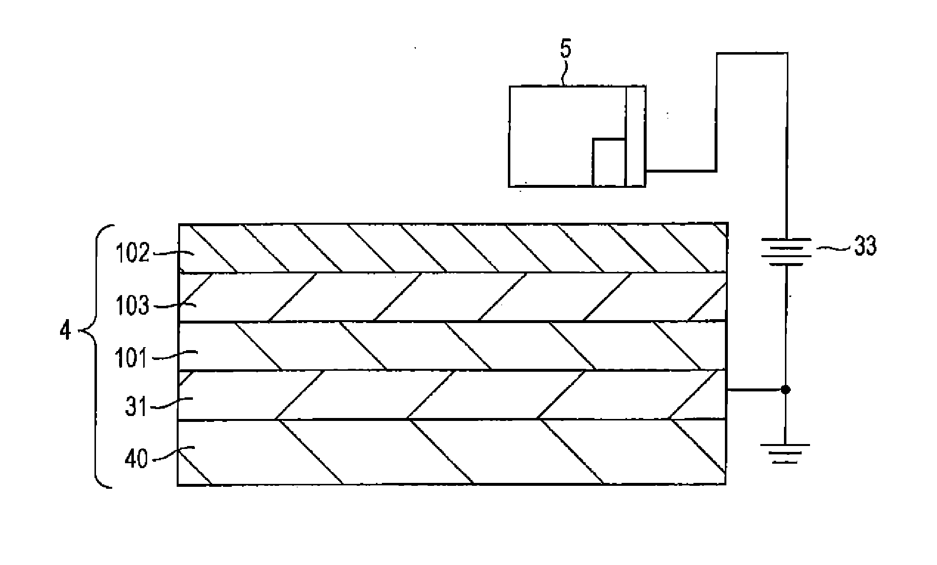
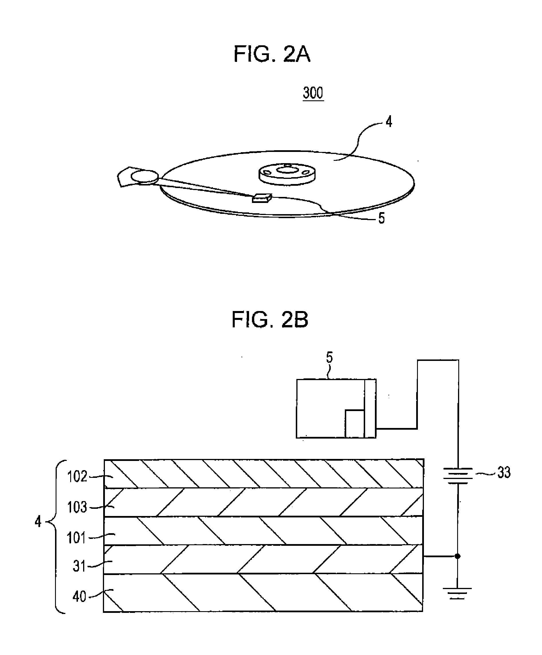
[0024]In a second embodiment, a case will be described in which a magnetization controlling element disclosed in the present invention is used as a recording medium of a magnetic recording system. FIG. 2A is a schematic view of a magnetic recording system 300 in the case where application to high-capacity magnetic recording, such as that in a hard disk, is assumed as a specific example of the second embodiment. In order to use the magnetization controlling element 200 utilizing the ME effect for a high-capacity magnetic recording medium 4, such as that a hard disk, it is required that a region in which magnetization reversal is caused by external manipulation can be restricted within a spatially limited range in the recording medium 4. For this purpose, a mechanism is necessary in which a magnetic field and an electric field to be applied are superimposed only in a spatially narrow region, and the superimposed region is moved to any given position on the recording medium 4. Head ass...
third embodiment
[0037]In a third embodiment, a description will be made on a magnetic recording system 400 in which an electric field and a magnetic field are not applied from a mechanism on a single recording head, but which includes, as a means for supplying an electric field more stably, a magnetic field applying mechanism 6 that has a function of applying a magnetic field and an electric field applying mechanism 7 that has a function of applying an electric field and that is disposed separately from the magnetic field applying mechanism 6. In the second embodiment, the case where the electric field applying mechanism and the magnetic field applying mechanism are configured on the same recording head has been described. However, it is not necessarily required to provide the magnetic field applying mechanism and the electric field applying mechanism on the same recording head. A structure shown in the third embodiment may be used as the means for applying a stable electric field to the first ME r...
PUM
 Abstract
Description
Claims
Application Information