Differential Adiabatic Compensation Calorimeter and Methods of Operation

a compensation calorimeter and adiabatic technology, applied in calorimeters, instruments, material thermal analysis, etc., can solve the problems of significant temperature excursion, single-channel scanning calorimeters, and devices without reference channels, so as to simplify testing procedures and eliminate control errors

Active Publication Date: 2015-05-07
WU FR L
View PDF7 Cites 0 Cited by
  • Summary
  • Abstract
  • Description
  • Claims
  • Application Information

AI Technical Summary

Benefits of technology

The present invention creates a " containerless" effect that results in total heat loss compensation, meaning the sample does not gain or lose heat to the sample container. This allows for real-world chemical process conditions to be used, and parameters obtained are readily scalable. The method is also more efficient and accurate than other compensation techniques because it only requires one feedback control parameter, the temperature difference between the sample and the reference container.

Problems solved by technology

Conversely, due to lack of sensitivity, the single-channel scanning calorimeter, i.e., the device without a reference channel, is not popular and mostly used for rough screening purpose.
One of the major disadvantages of temperature scanning calorimetry is that the time-resolved thermochemical information cannot be experimentally obtained.
When chemical mixing, reaction or decomposition becomes exothermic, the heat released from the sample may cause a significant temperature excursion, and sometimes develop into a self-perpetuated, thermal runaway reaction.
However, this single-channel calorimeter is a quasi-adiabatic device, since a large portion of the heat released by sample is absorbed by or sinks to the sample container.
Because this heat sink effect, the experimental temperature rise and the rate of temperature rise are, therefore, dampened or lower than the theoretical limits, causing a so-called “thermal lag” effect that significantly slows down the reaction progress and results in an erroneous time to maximum rate (TMR), a critical value in runaway reaction hazard assessment.
However not only did the device fail to deliver a calorimetric result better than 95%, it also is difficult to downsize this liter-scale container to meet the analytical lab standards, and therefore has never been commercialized.
However, these scanning devices are neither adiabatic nor isothermal, therefore, the time-resolved temperature and pressure information, such as the maximum adiabatic temperature rise and time to maximum rate (TMR), can't be measured on these devices.
Although the differential compensation principle has been used in the instrument design of several commercial isothermal and DSC calorimeters, it has never been used in adiabatic calorimetry.

Method used


Image

  • Differential Adiabatic Compensation Calorimeter and Methods of Operation
  • Differential Adiabatic Compensation Calorimeter and Methods of Operation
  • Differential Adiabatic Compensation Calorimeter and Methods of Operation

Examples


Embodiment Construction

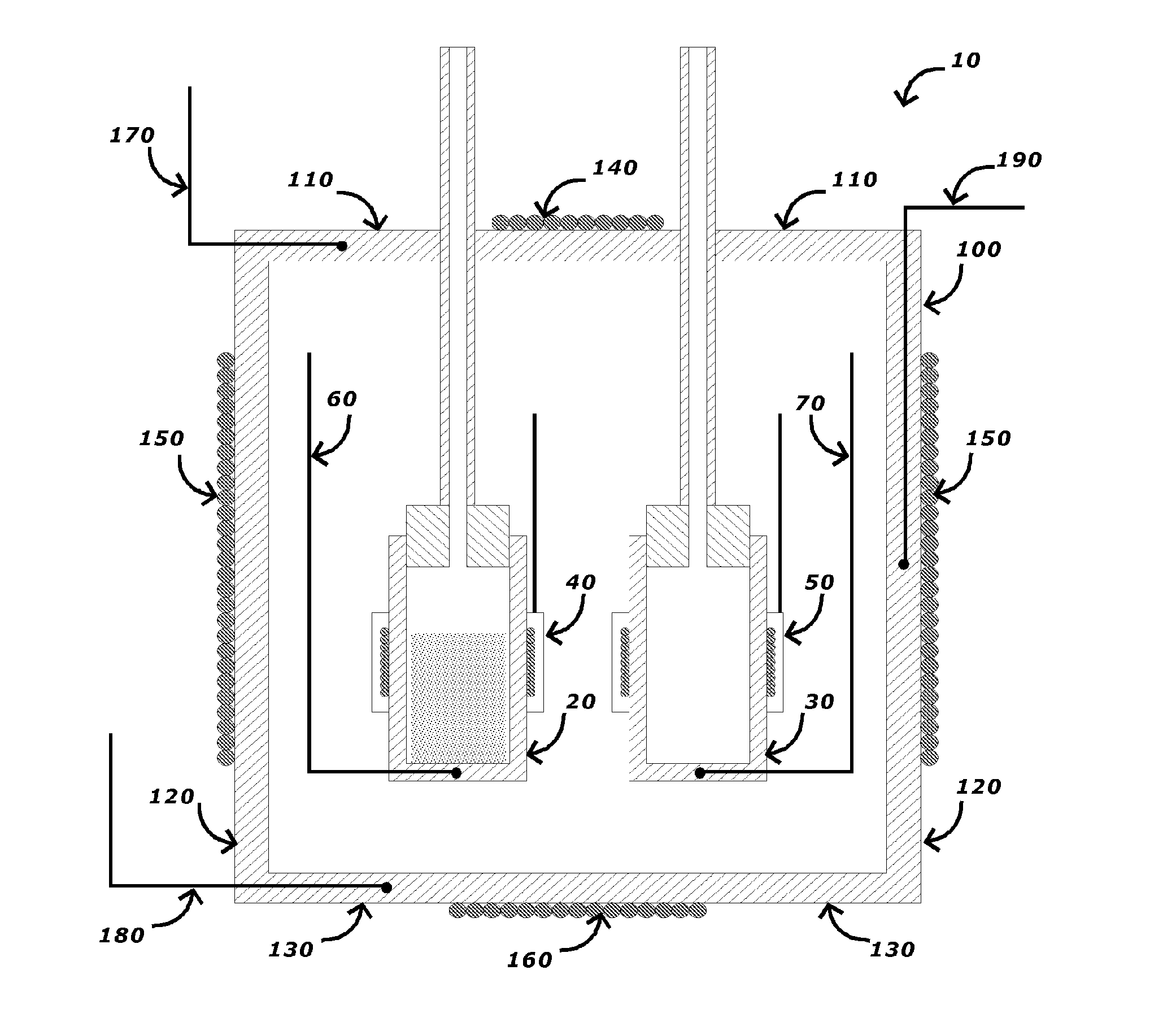
[0021]A cross-sectional view of an embodiment of a differential adiabatic compensation calorimeter is shown in FIG. 1. As shown in FIG. 1, the calorimeter 10 comprises: a sample container 20, a reference container 30; a heat compensation control system, and an adiabatic chamber 100 disposed around the sample container 20 and the reference container 30, and a chamber temperature control system. In a preferred embodiment, the sample container 20 and the reference container 30 have an identical construction to minimize any differences in their thermal behavior.

[0022]In an embodiment, the sample container 20 is disposed within an adiabatic chamber 100. The sample container 20 may be made from any suitable materials for the desired sample conditions (e.g., temperature, pressure, chemical composition, etc.). Suitable materials for the sample container 20 include, but are not limited to, various metals such as stainless steels, titanium alloys, Monel™ alloys, Hastelloy C™ alloys and combin...


PUM


Abstract

The differential adiabatic compensation calorimeter comprises sample and reference containers, sample and reference temperature sensors connected back-to-back, in series, sample and reference compensating heaters coupled to the sample and reference containers, and a temperature-controlled chamber. In this differential adiabatic mixing and reaction calorimeter, the sample heat-sink heat loss to the sample container is compensated so that the exothermic reaction is conducted in an adiabatic state, resulting in an undistorted adiabatic process gaining the highest adiabatic temperature rise that corresponds to the theoretical value and an experimentally measured time to maximum rate value. The calorimeter is designed for measuring the time-resolved adiabatic temperature rise, the rate of temperature rise, the time to maximum temperature peak and time to maximum rate of an exothermic chemical reaction.

Description

CROSS-REFERENCE TO RELATED APPLICATIONS[0001]This application is a continuation of U.S. patent application Ser. No. 12 / 830,825, filed Jul. 6, 2010, which claims priority to U.S. Provisional Application No. 61 / 223,552, filed Jul. 7, 2009, which applications are entirely incorporated by reference herein.TECHNICAL FIELD[0002]This disclosure relates generally to the field of adiabatic calorimeter devices and methods of operation, and more particularly to a differential adiabatic calorimeter using a differential adiabatic compensation technique.BACKGROUND OF THE INVENTION[0003]calorimetry is a universal analytical method that measures heat or heat release rate from a biological, chemical or physical sample or process. There are three main categories of calorimeters: temperature scanning calorimeters, isothermal and adiabatic. Differential scanning calorimeter is the most popular temperature scanning calorimeter in which the difference in the form of heat or temperature between the sample...

Claims


Application Information

Patent Timeline
Patent Type & Authority Applications(United States)
IPC IPC(8): G01K17/04G01N25/48
CPCG01N25/4826G01K17/04G01N25/4866
Inventor WU, FRANK L.
Owner WU FR L
Why Eureka
Try Eureka