Steam Turbine Forced Air Cooling System, Equipment, and Steam Turbine Equipped with it

Active Publication Date: 2015-05-07
MITSUBISHI POWER LTD
View PDF4 Cites 4 Cited by
  • Summary
  • Abstract
  • Description
  • Claims
  • Application Information

AI Technical Summary

Benefits of technology

[0021]The present invention can improve a cooling effect by the use of a device that is easy to get when the st

Problems solved by technology

However, the above technology has a problem as below.
Since the cooling air is sucked by the existing vacuum pump, the amount of cooling air introduced into the steam turbine is limited by the capacity and suction capability of the vacuum pump.
Thus, it used to be difficult to improve the cooling capability by increasing the amount of cooling air.
Thus, there is a problem in that the de

Method used


Image

  • Steam Turbine Forced Air Cooling System, Equipment, and Steam Turbine Equipped with it
  • Steam Turbine Forced Air Cooling System, Equipment, and Steam Turbine Equipped with it
  • Steam Turbine Forced Air Cooling System, Equipment, and Steam Turbine Equipped with it

Examples


Example

First Embodiment

[0029]A first embodiment of a steam turbine forced air cooling system, its method, and a steam turbine provided with the system will be described with reference to FIGS. 1 and 2. The present embodiment describes a case where the present invention is applied to a steam turbine including a HP turbine, an IH turbine, and a LP turbine as an example in FIGS. 1 and 2.

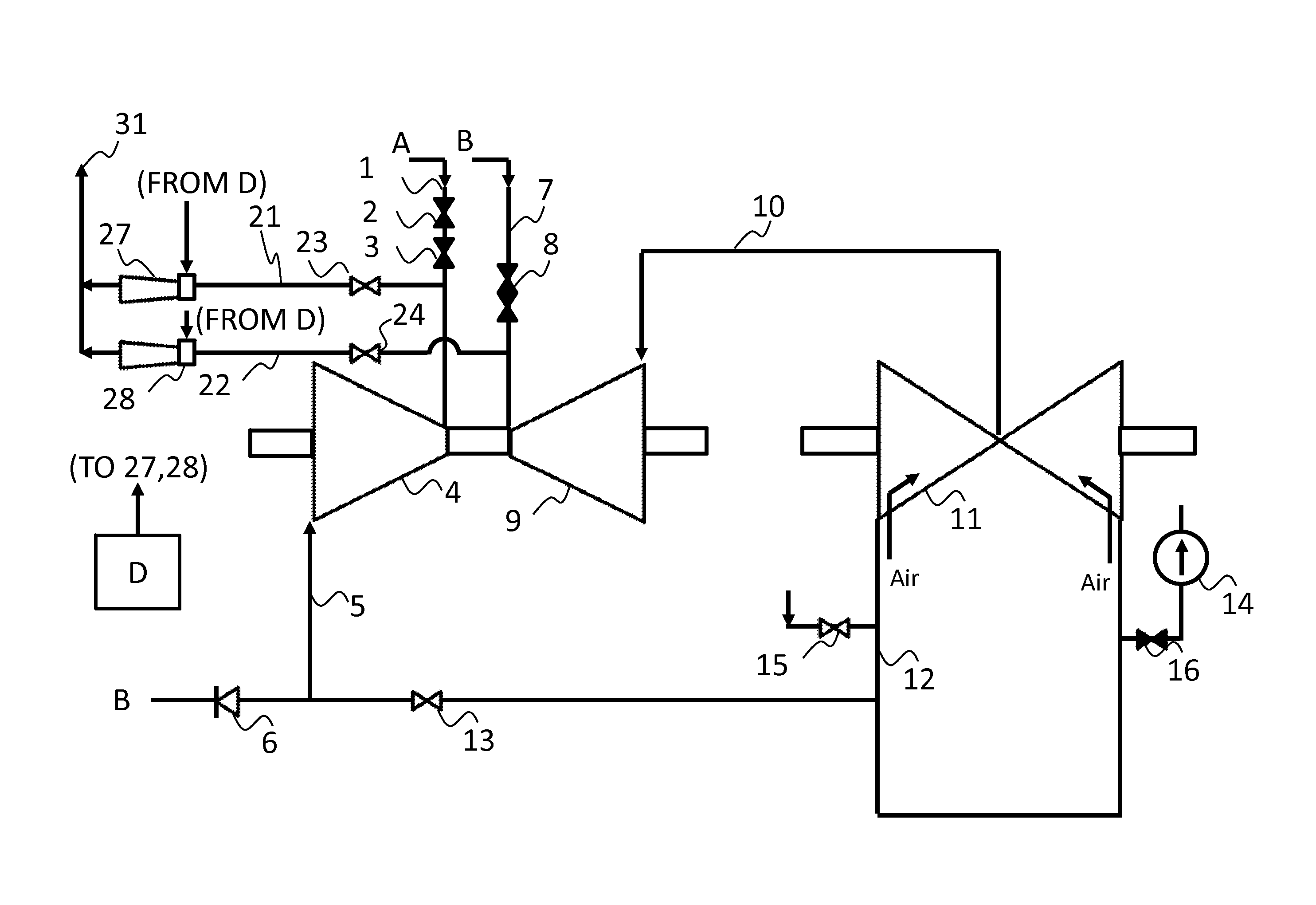
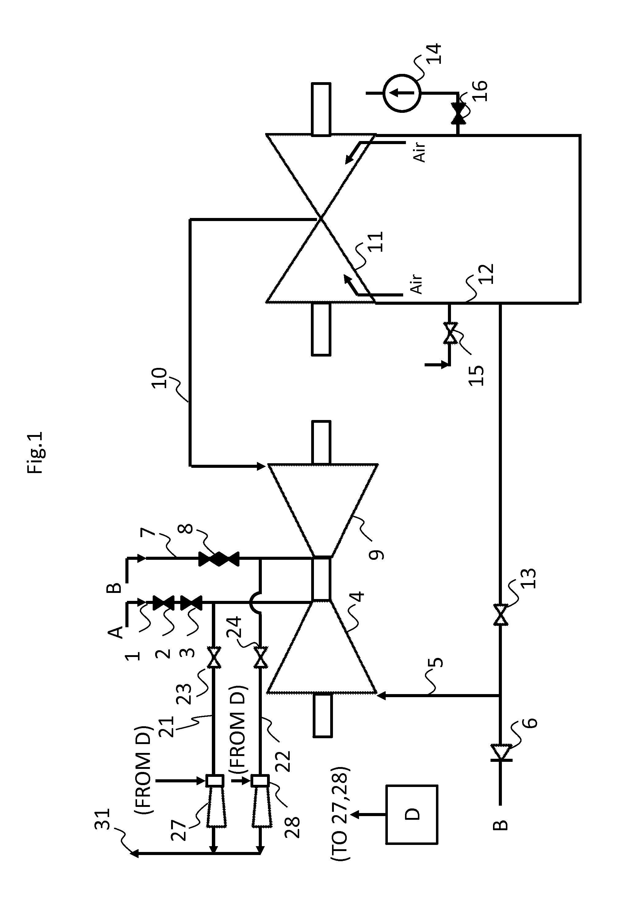
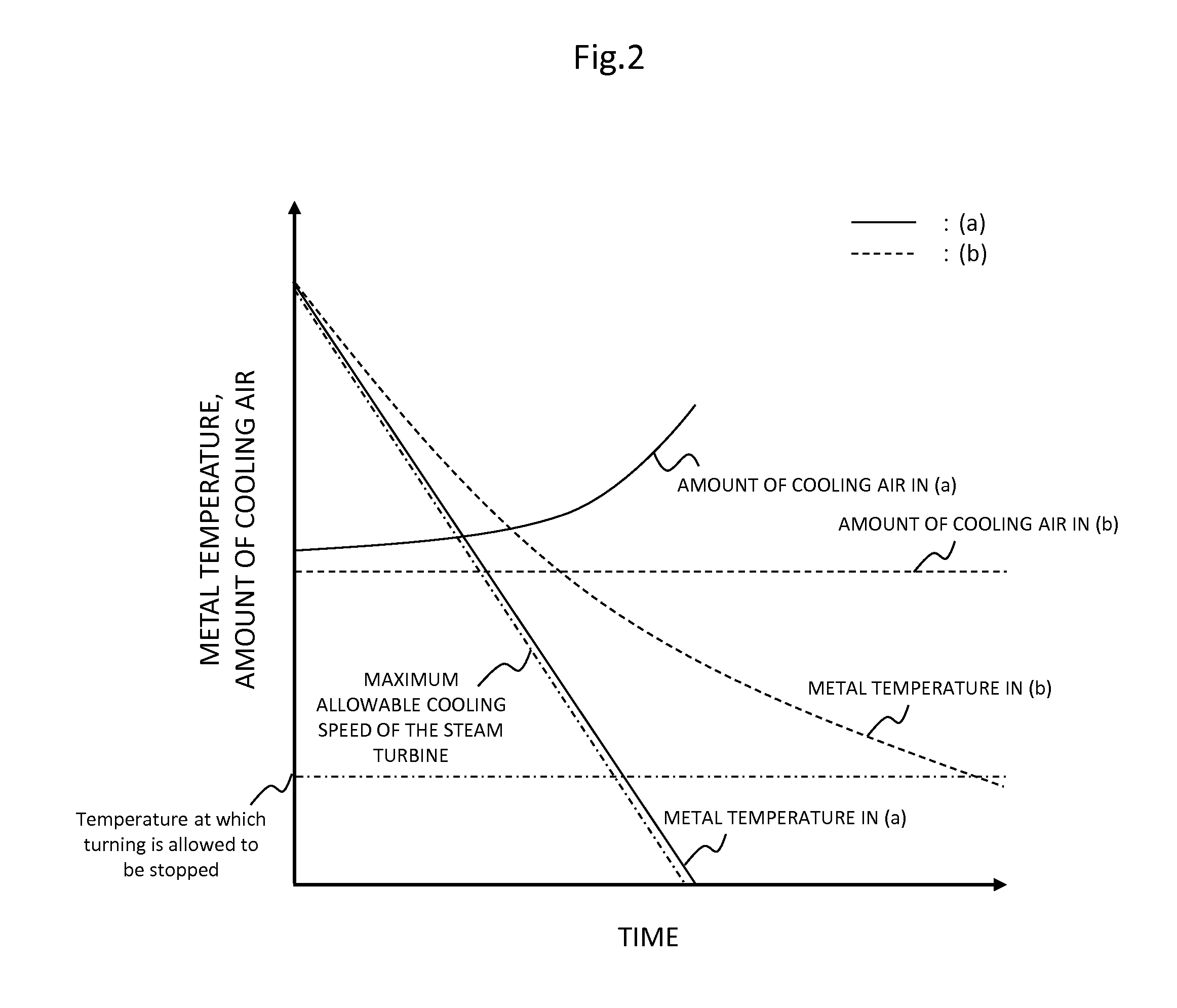
[0030]FIG. 1 illustrates a rough schema of a system of the steam turbine provided with the steam turbine forced air cooling system according to the first embodiment of the present invention. FIG. 2 is a graph illustrating a relation between steam turbine metal temperature and an amount of cooling air according to the first embodiment of the present invention.

[0031]As illustrated in FIG. 1, the steam turbine includes several types of turbines associated with pressure, such as a HP turbine 4, an IP turbine 9, and a LP turbine 11.

[0032]In the steam turbine as described above, steam generated in a boiler A is intr...

Example

Second Embodiment

[0052]A second embodiment of a steam turbine forced air cooling system, its method, and a steam turbine provided with the system will be described with reference to FIGS. 3 and 4.

[0053]FIG. 3 illustrates a rough schema of a system of a steam turbine provided with a steam turbine forced air cooling system according to a second embodiment of the present invention. FIG. 4 is a graph illustrating pressures at various portions of the steam turbine according to the second embodiment of the present invention.

[0054]With reference to FIG. 3, the steam turbine forced air cooling system of the present embodiment is such that seats, e.g., manhole seats 34, 35 for maintenance installed on the condenser 12; branch pipes 41 and 42 respectively branched off from the manhole seats 34 and 35; valves 39 and 40 respectively installed in the branch pipes 41 and 42; a blower 36 installed on the branch pipes 41, 42; pressure detectors 37, 38 installed close to an atmospheric relief diaphr...

Example

Third Embodiment

[0064]A third embodiment of a steam turbine forced air cooling system, its method, and a steam turbine provided with the system will be described with reference to FIG. 5.

[0065]FIG. 5 illustrates an outline of the system of a steam turbine provided with a steam turbine forced air cooling system according to a third embodiment of the present invention.

[0066]With reference to FIG. 5, the steam turbine forced air cooling system of the present embodiment is such that a branch pipe 45 branched off from an extraction pipe 43 disposed on the HP turbine 4, a branch pipe 46 branched off from an extraction pipe 44 disposed on the IP turbine 9, and stop valves 32, 33 and ejectors 29, 30 installed on the corresponding branch pipes 45, 46 are further attached to the steam turbine forced air cooling system of the first embodiment.

[0067]The configurations other than this are almost the same as those of the steam turbine forced air cooling system of the first embodiment and hence th...


PUM


Abstract

The invention offers a steam turbine forced air cooling system, its method, and a steam turbine provided with the system, the system being of an inexpensive and simple device configuration and improving a cooling effect by the use of an easy-to-get device.
Suction is applied to the steam introduction side of an HP turbine 4 or an IP turbine 9 by the use of cooling air suction ejectors 27, 28 which use a compressed medium other than steam as a drive source. The cooling air is then introduced from the steam exhaust portion of the steam turbine into the inside of the steam turbine and is discharged from the ejectors 27, 28 to the atmosphere.

Description

BACKGROUND OF THE INVENTION[0001]1. Field of the Invention[0002]The present invention relates to a steam turbine forced air cooling system for forcibly cooling a steam turbine after the shutdown of the steam turbine, a steam turbine provided with the system, and a method of the steam turbine forced air cooling.[0003]2. Description of the Related Art[0004]A steam turbine introduces high-temperature steam of 500 degrees Celsius or higher at a steam turbine inlet portion. Such a steam turbine requires disassembly operation at the time of routine inspection or failure of the turbine itself. It would take a considerable period of time if the steam turbine is cooled through natural heat-release to a temperature at which turning can be stopped. In addition, electric power cannot be supplied in such a period of time. It is hence desirable to shorten a cooling-down period as much as possible with the stable supply and economic efficiency of electric power taken into consideration.[0005]JP-19...

Claims


Application Information

Patent Timeline
IPC IPC(8): F01D25/12
CPCF01D25/12F05D2260/232F05D2220/31F01D21/00F01D25/24F01K5/02F02C7/12
Inventor KASHIMA, GENKIMASUDA, TOYOHIKOHINUMA, TETSUYASAGAWA, ISAONARIMATSU, YOSHITAKAKOBAYASHI, HOTAKALEE, GOINGWONSASAKI, KENJI
Owner MITSUBISHI POWER LTD
Why Eureka
Try Eureka