

Hydrogen Generation Apparatus
- Summary
- Abstract
- Description
- Claims
- Application Information
AI Technical Summary
Benefits of technology
Problems solved by technology
Method used
Image

Examples
first embodiment
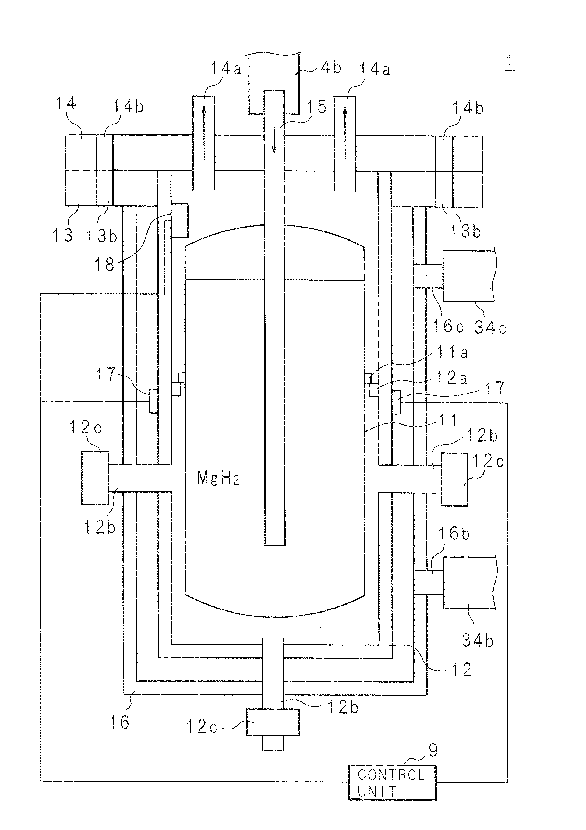
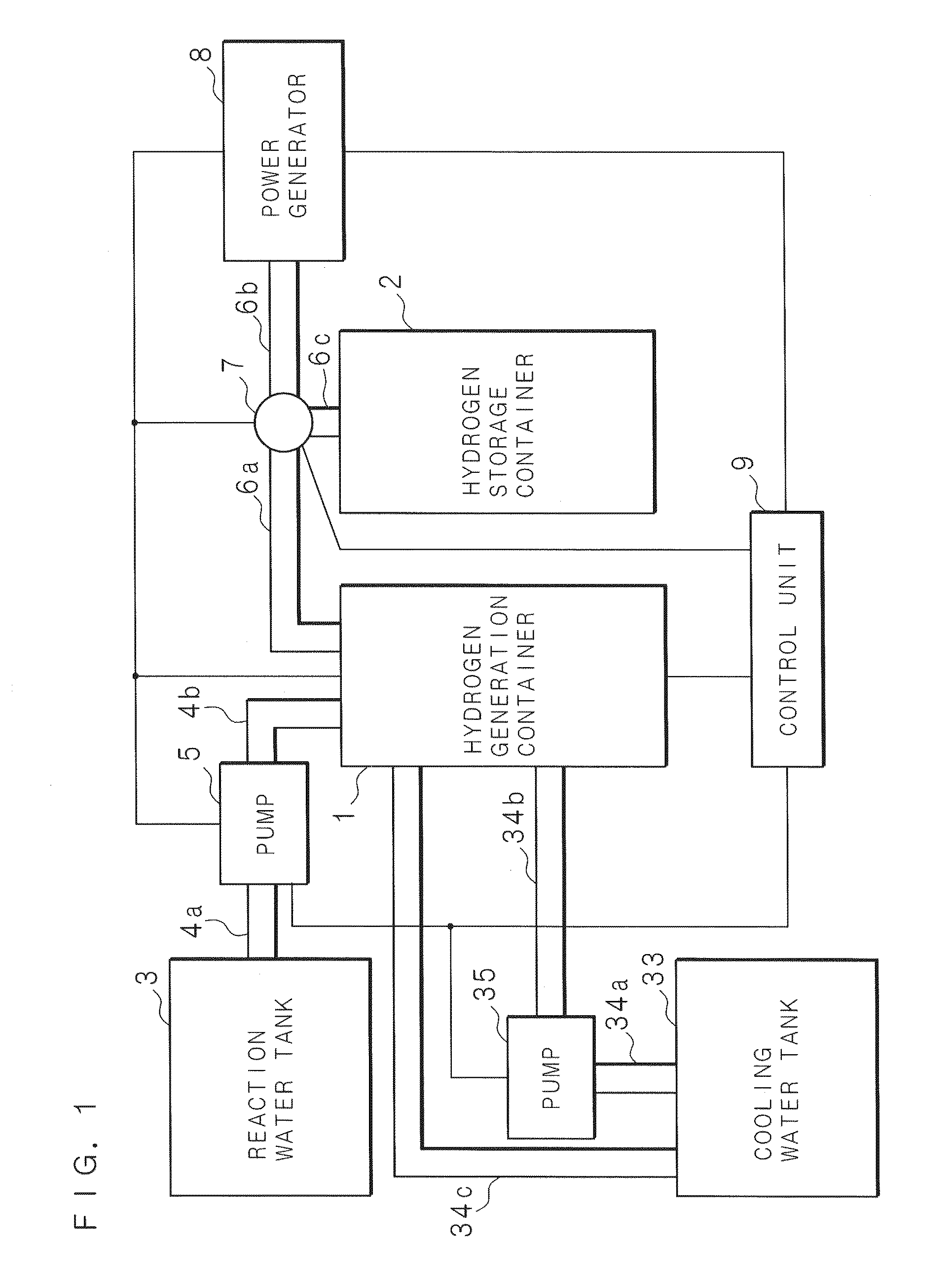
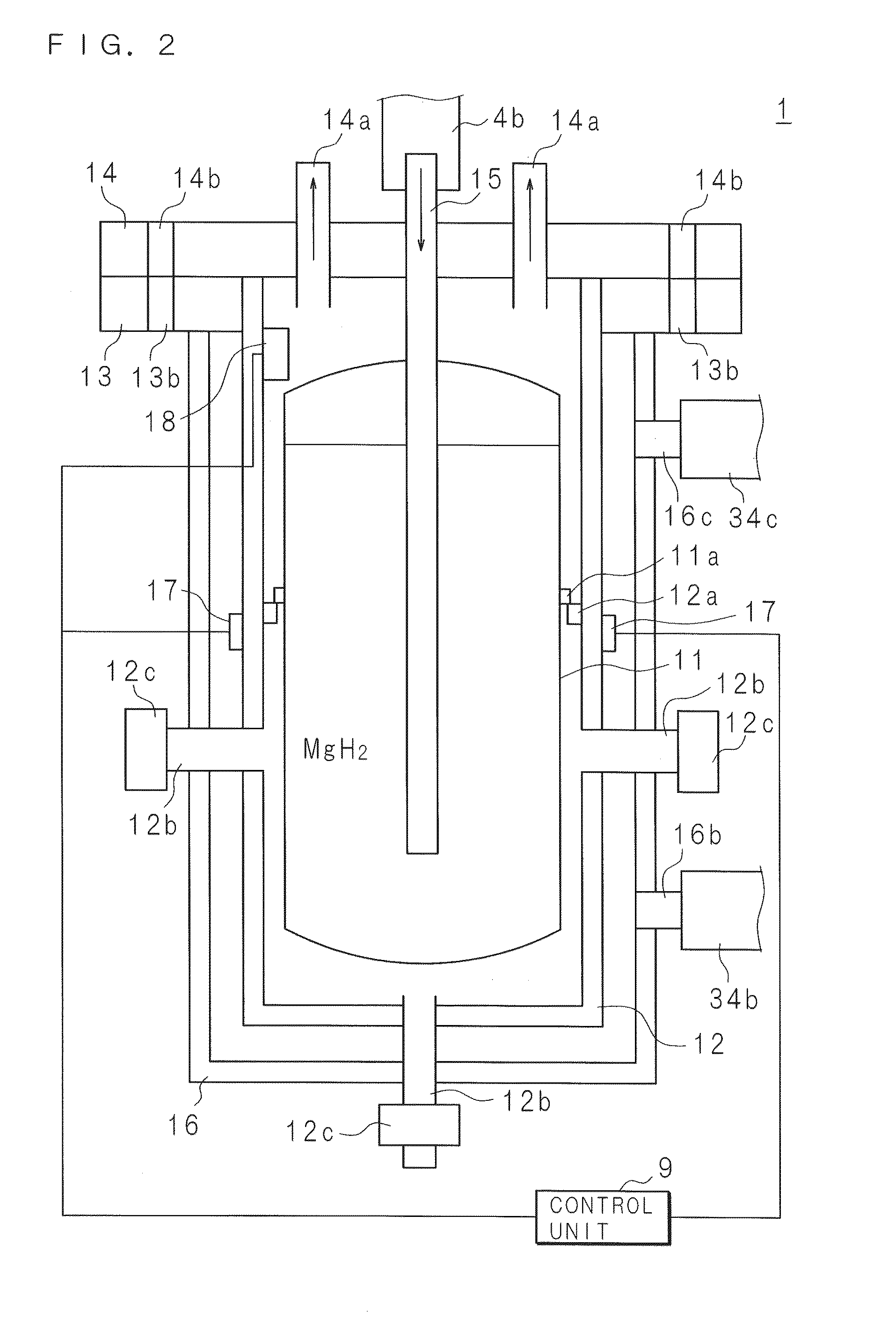
[0042]An embodiment of the present invention is described below. FIG. 1 is a block diagram illustrating a configuration of a hydrogen generation apparatus. The hydrogen generation apparatus includes: a reaction water tank 3 storing water used for a hydrolysis reaction; a pipe 4a whose one end is connected to the reaction water tank 3, a pump 5 connected to the other end of the pipe 4a; a pipe 4b whose one end is connected to the pump 5, a cooling water tank 33 storing cooling water; pipes 34a and 34c one end of each of which is connected to the cooling water tank 33, a pump 35 connected to the other end of the pipe 34a; a pipe 34b whose one end is connected to the pump 35, a hydrogen generation container 1 connected to the other end of each of the pipes 4b, 34b, and 34c; a pipe 6a whose one end is connected to the hydrogen generation container 1; an on-off valve 7 provided at the other end of the pipe 6a; a hydrogen storage container 2 connected through the pipe 6c to the on-off val...
second embodiment
[0067]A second embodiment is described below. In the present embodiment, temperature adjustment of the hydrogen generation part 12 is performed by air cooling in place of water cooling so that temperature adjustment is achieved.
[0068]FIG. 5 is a schematic vertical sectional view illustrating the hydrogen generation container 1. The hydrogen generation container 1 in the present embodiment is provided with an air blow unit 36 serving as a temperature adjustment part. The air blow unit 36 is a fan whose blades are driven by an electric motor. The air blow unit 36 is arranged at a position and in a direction such that wind at the time of operation hits the hydrogen generation part 12. Further, the air blow unit 36 is controlled by the control unit 9 such that air blowing is started or stopped on the basis of the temperature measured by the thermometer 17. The thermometer 17 is provided in the outer surface of the hydrogen generation part 12 and, instead, may be provided on the inner si...
third embodiment
[0071]A third embodiment is described below. In the present embodiment, dehumidification and deodorization is performed on the hydrogen generated by the hydrogen generation part 12.
[0072]FIG. 6 is a block diagram illustrating a configuration of a hydrogen generation apparatus provided with a dehumidification section 41. In the present embodiment, the dehumidification section 41 is provided between pipes 43a and 43b. For example, the dehumidification section 41 is a container in which a hole leading to the inside is provided at each of two sites in the outer surface and the inside of which is filled with zeolite. Among the holes of the dehumidification section 41, one is connected to the pipe 43a connected to the hydrogen generation container 1 and the other is connected to the pipe 43b connected to the hydrogen storage container 2. When the hydrogen sent through the pipe 43a goes through the dehumidification section 41, moisture is adsorbed by zeolite so that dehumidification is ach...
PUM
 Abstract
Description
Claims
Application Information