
Exhaust emission purifying apparatus and exhaust emission purifying method for engine

a technology of exhaust gas purification and purification apparatus, which is applied in the direction of machines/engines, exhaust treatment electric control, separation processes, etc., can solve the problems of urea aqueous solution being insufficient, urea being deposited, exhaust gas pressure rising or fuel consumption degrading, etc., to suppress the deposition of urea and accelerate the hydrolysis reaction

Inactive Publication Date: 2006-10-19
NISSAN DIESEL MOTOR CO
View PDF24 Cites 21 Cited by
  • Summary
  • Abstract
  • Description
  • Claims
  • Application Information

AI Technical Summary

Benefits of technology

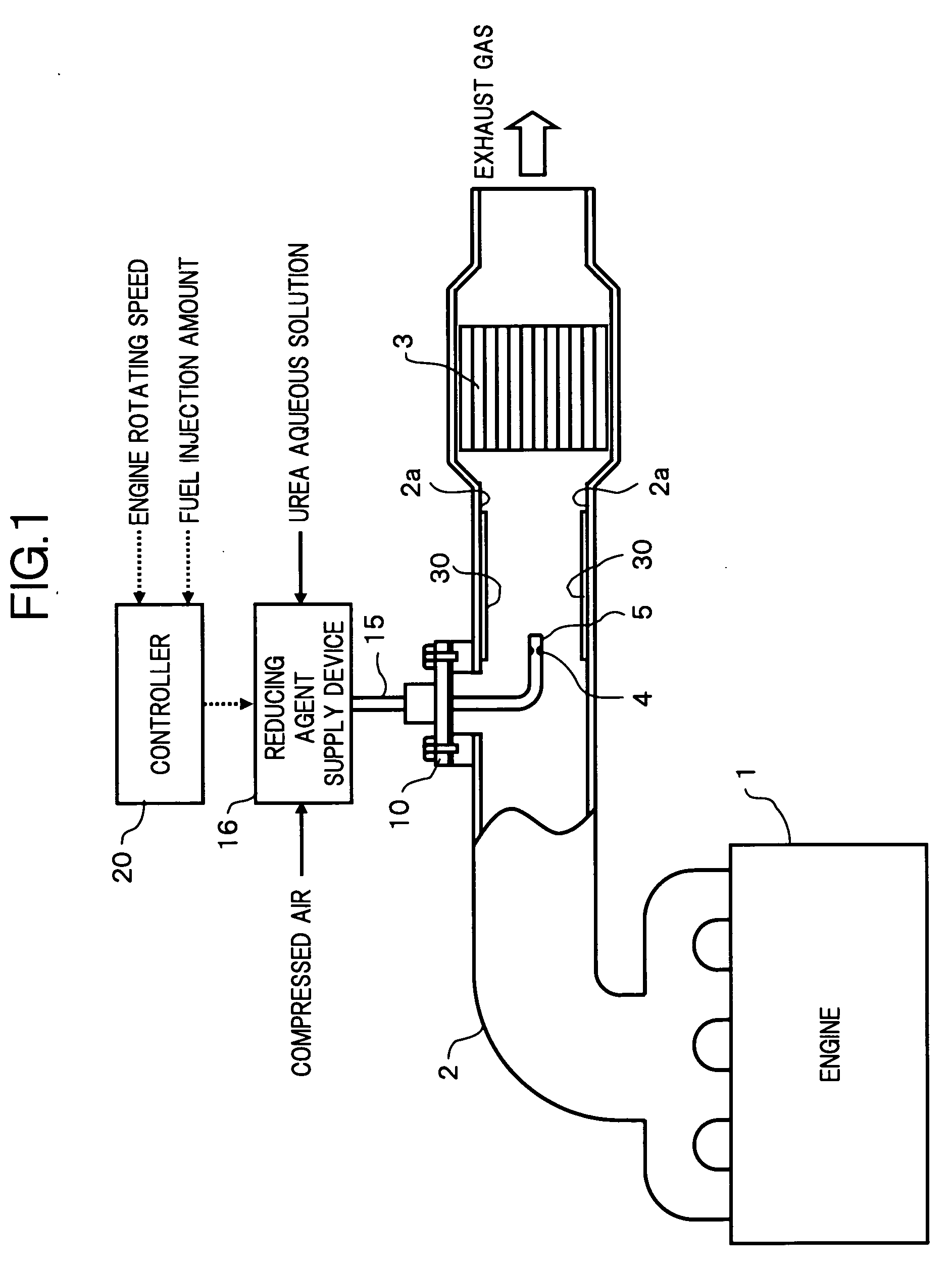
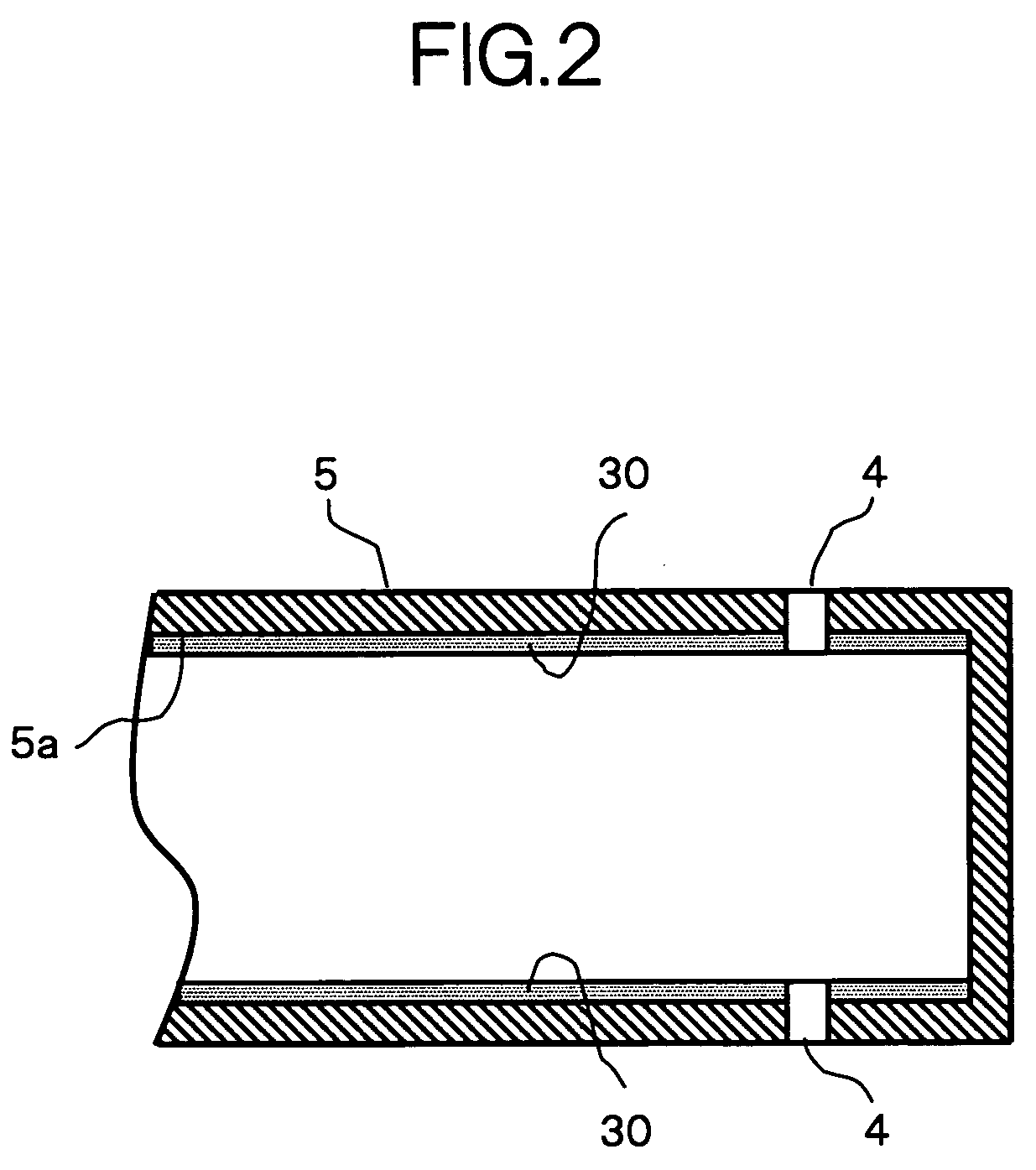
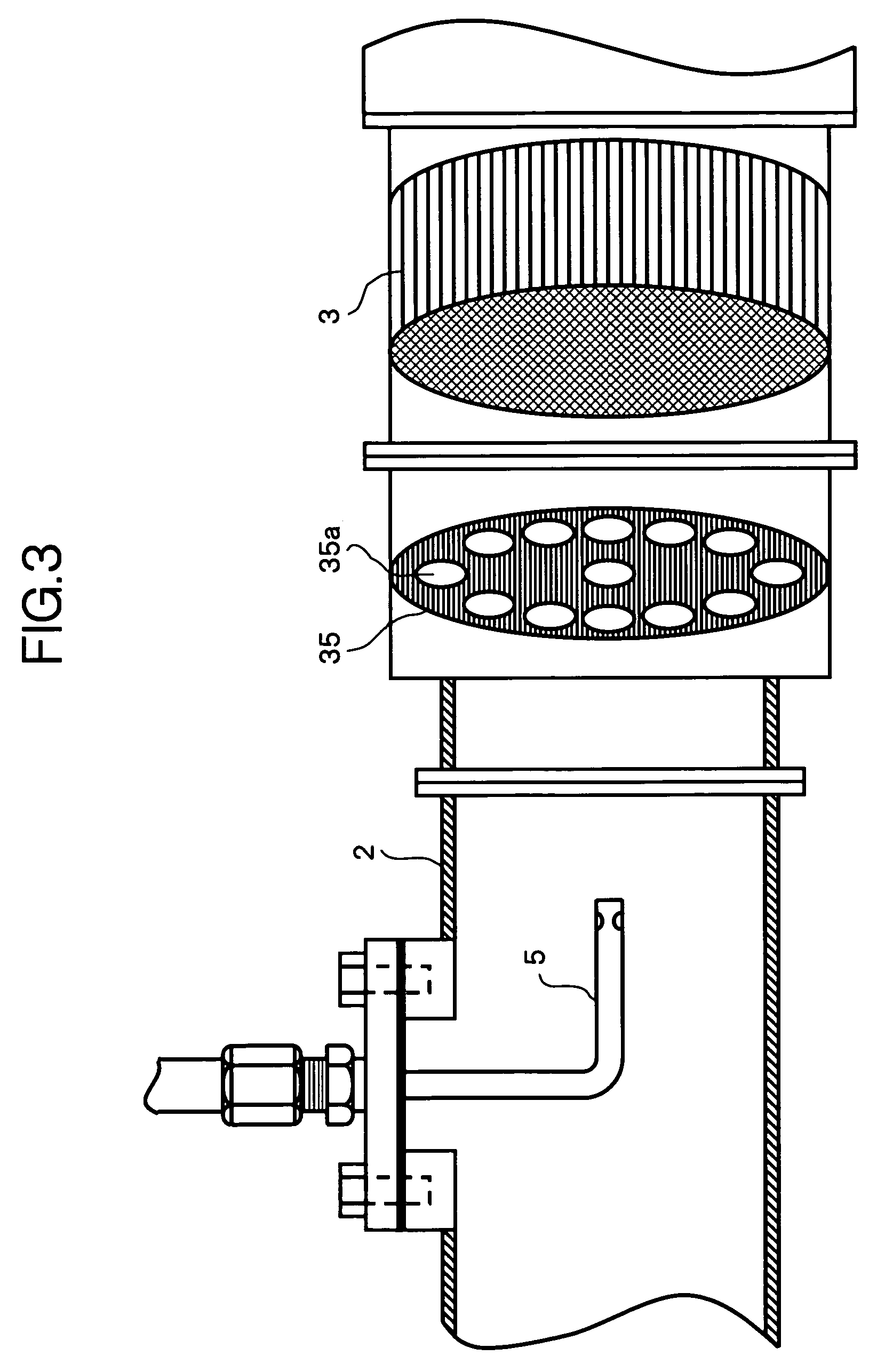
[0010] With the exhaust emission purifying technology for the engine according to the present invention, nitrogen oxides contained in the exhaust gas of the engine is reductively purified in the reduction catalytic converter using ammonia produced by the urea aqueous solution. At this time, if the hydrolytic catalyst is applied to the inner passage of the injection nozzle, since the urea aqueous solution is in contact with the hydrolytic catalyst when it passes through the injection nozzle, the hydrolysis reaction of the urea aqueous solution is accelerated. Further, if the hydrolytic catalyst is applied to the exhaust pipe positioned between the injection nozzle and the reduction catalytic converter, even if liquid drops of the urea aqueous solution attach to an inner wall of the exhaust pipe, since such liquid drops are in contact with the hydrolytic catalyst, the hydrolysis reaction of the liquid drops of the urea aqueous solution is accelerated. Moreover, if the hydrolytic catalyst is applied to the diffuser panel, since the urea aqueous solution is in contact with the hydrolytic catalyst when it passes through the diffuser panel, the hydrolysis reaction of the urea aqueous solution is accelerated. Therefore, the deposition of urea is suppressed, so that urea is hardly accumulated in the exhaust pipe. Consequently, it is possible to suppress the rise of exhaust gas pressure, the degradation of fuel consumption, and the like.
[0011] Moreover, if the hydrolytic catalyst is applied to the inner passage of the injection nozzle, even if the liquid drops of the urea aqueous solution attach to the inner passage when the injection supply of the urea aqueous solution is stopped, these liquid drops are in contact with the hydrolytic catalyst, so that the hydrolysis reaction of the urea aqueous solution is accelerated. Therefore, the deposition of urea is suppressed, so that urea is hard to be accumulated in the inner passage of the injection nozzle. Consequently, the clogging of the injection nozzle is suppressed.

Problems solved by technology

However, in the above described conventional exhaust emission purifying apparatus, when an amount of injection-supply flow of the urea aqueous solution is large in relation to the temperature and a flow amount of the exhaust gas, the hydrolysis of the urea aqueous solution is insufficient, and therefore, only the water content may be evaporated from the urea aqueous solution, resulting in the urea being deposited.
Then, if the urea is accumulated on the wall of the exhaust pipe, since such accumulated urea prevents the smooth flowing of the exhaust gas, so as to increase resistance against flow of the exhaust gas, there is a possibility that the exhaust gas pressure rises or the fuel consumption is degraded.

Method used


Image

  • Exhaust emission purifying apparatus and exhaust emission purifying method for engine
  • Exhaust emission purifying apparatus and exhaust emission purifying method for engine
  • Exhaust emission purifying apparatus and exhaust emission purifying method for engine

Examples


Embodiment Construction

[0015] The present invention will be described referring to the appended drawings hereunder.

[0016]FIG. 1 shows an entire configuration of an exhaust emission purifying apparatus for an engine, which realizes the present invention.

[0017] In an exhaust pipe 2 of an engine 1, a NOx reduction catalytic converter 3 which reductively purifies NOx by using ammonia produced by the urea aqueous solution, is disposed. Further, on the exhaust upstream of the NOx reduction catalytic converter 3, an injection nozzle 5 which injects to supply the urea aqueous solution via a nozzle hole 4 opened to the inside of the exhaust pipe 2, is disposed. The injection nozzle 5 is supportively fixed in a cantilevered state via a flange 10 which is detachably mounted on a peripheral wall of the exhaust pipe 2, so that a tip end thereof extends to the exhaust downstream along approximately the center of axle of the exhaust pipe 2, and also, is communicatively connected to a reducing agent supply device 16 vi...


PUM


Abstract

In an exhaust emission purifying apparatus for an engine provided with: a NOx reduction catalytic converter disposed in an engine exhaust pipe, for reductively purifying NOx with ammonia produced by the urea aqueous solution; and an injection nozzle injection-supplying the urea aqueous solution into the exhaust gas at an upstream position of the NOx reduction catalytic converter, a hydrolytic catalyst that accelerates the hydrolysis reaction by which ammonia is produced by the urea aqueous solution, is applied to at least one of an inner passage of the injection nozzle, the exhaust pipe positioned between the injection nozzle and the NOx reduction catalytic converter, and a diffuser panel diffusing the exhaust gas between the injection nozzle and the reduction catalytic converter, and then, the hydrolysis reaction of the urea aqueous solution being in contact with the hydrolytic catalyst is accelerated, to thereby suppress the deposition of urea in the exhaust pipe.

Description

[0001] This application is a continuation of PCT / JP2004 / 012745, filed on Sep. 2, 2004.BACKGROUND OF THE INVENTION [0002] 1. Field of the Invention [0003] The present invention relates generally to an exhaust emission purifying technology for an engine, in which nitrogen oxides (NOx) in the exhaust gas is reductively purified by using ammonia produced by the urea aqueous solution that is injection-supplied into an exhaust pipe, and in particular, relates to a technology for suppressing the deposition of urea into the exhaust pipe of the engine. [0004] 2. Description of the Related Art [0005] Japanese Unexamined Patent Publication No. 2000-27627 discloses an exhaust emission purifying apparatus as a proposal for a catalytic converter purifying system for reductively purifying NOx contained in the exhaust gas of an engine. [0006] In such a conventional exhaust emission purifying apparatus, a NOx reduction catalytic converter is disposed in an exhaust pipe of the engine, and a reducing ...

Claims


Application Information

Patent Timeline
IPC IPC(8): B01D53/56B01D53/94F01N3/24C01C1/08F01N1/08F01N3/08F01N3/10F01N3/20F01N3/28F01N9/00
CPCF01N3/2066F01N3/36F01N2240/20F01N2240/40F01N2510/14Y02T10/24F01N2610/1453B01F5/0451B01F5/0463B01F5/0688B01F3/04049F01N2610/02Y02T10/12B01F23/2132B01F25/3131B01F25/31331B01F25/4521
Inventor HIRATA, KIMINOBUSATOU, HIROKAZU
Owner NISSAN DIESEL MOTOR CO
Learn More