Thermal Stimulation Probe And Method

a thermal stimulation and tissue technology, applied in the field of improved tissue thermal stimulation, can solve the problems of not finding widespread clinical use of methods, the difficulty of selecting the activation with subsequent recording for the evaluation of c-fiber activity, and the general difficulty of determining if tissue about to be damaged serves a crucial brain function, etc., to achieve simple, small and cheaper construction and operation.

Inactive Publication Date: 2015-05-07
MEDOC
View PDF11 Cites 17 Cited by
  • Summary
  • Abstract
  • Description
  • Claims
  • Application Information

AI Technical Summary

Benefits of technology

[0023]A thermal sensory analyzer system is provided, with limited parameter ranges which enable simpler, smaller and cheaper construction and operation. The thermal sensory analyzer system is a QST (Quantitative Sensory Testing) device including advanced software package designed for clinical use and advance research in the field of pain management as well as neurology and neurophysiology.

Problems solved by technology

However, selective activating with subsequent recording for the evaluation of C-fibers activity is apparently more difficult.
These methods, however, have not found widespread clinical use, possibly due to their complexity and / or poor sensation generation quality.
During brain surgery there is a general difficulty of determining if tissue about to be damaged serves a crucial brain function.
Due to the difficult in determining if the correct effect has been achieved, there exists a problem of patients which are immobilized but are conscious and / or feel pain during surgery.
Even if not conscious, pain can cause an increase in sensed or even chronic pain after surgery.
Moreover, in the presence of additional underlying medical conditions such as Diabetes, skin biopsy is considered harmful.
Even without presence of central pain, sensory symptoms can be disturbing and an impact on patient quality of life.
To achieve such goals, the systems were not optimized for clinical testing and screening use.
For example, systems of the art use liquid heat exchangers which are cumbersome, expensive and less reliable.

Method used


Image

  • Thermal Stimulation Probe And Method
  • Thermal Stimulation Probe And Method
  • Thermal Stimulation Probe And Method

Examples


Embodiment Construction

[0102]Before explaining at least one embodiment of the invention in detail, it is to be understood that the invention is not limited in its application to the details of construction and the arrangement of the components set forth in the following description or illustrated in the drawings. The invention is capable of other embodiments or of being practiced or carried out in various ways. Also, it is to be understood that the phraseology and terminology employed herein is for the purpose of description and should not be regarded as limiting.

[0103]For clarity, non-essential elements were omitted from some of the drawings.

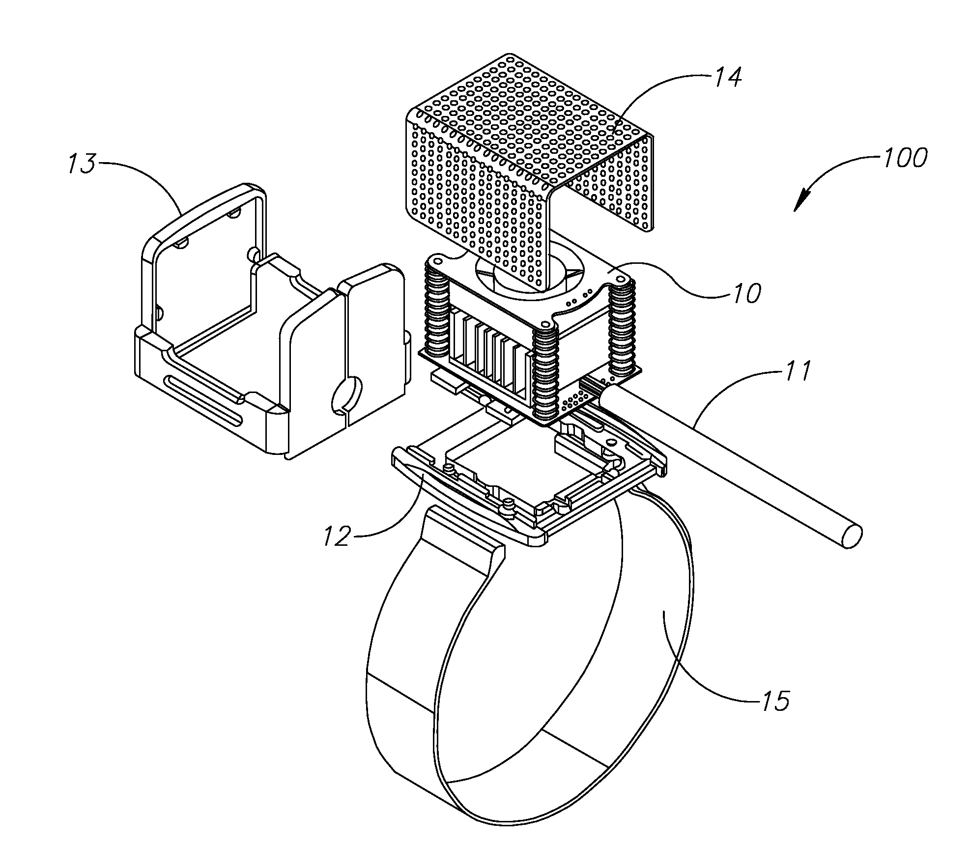
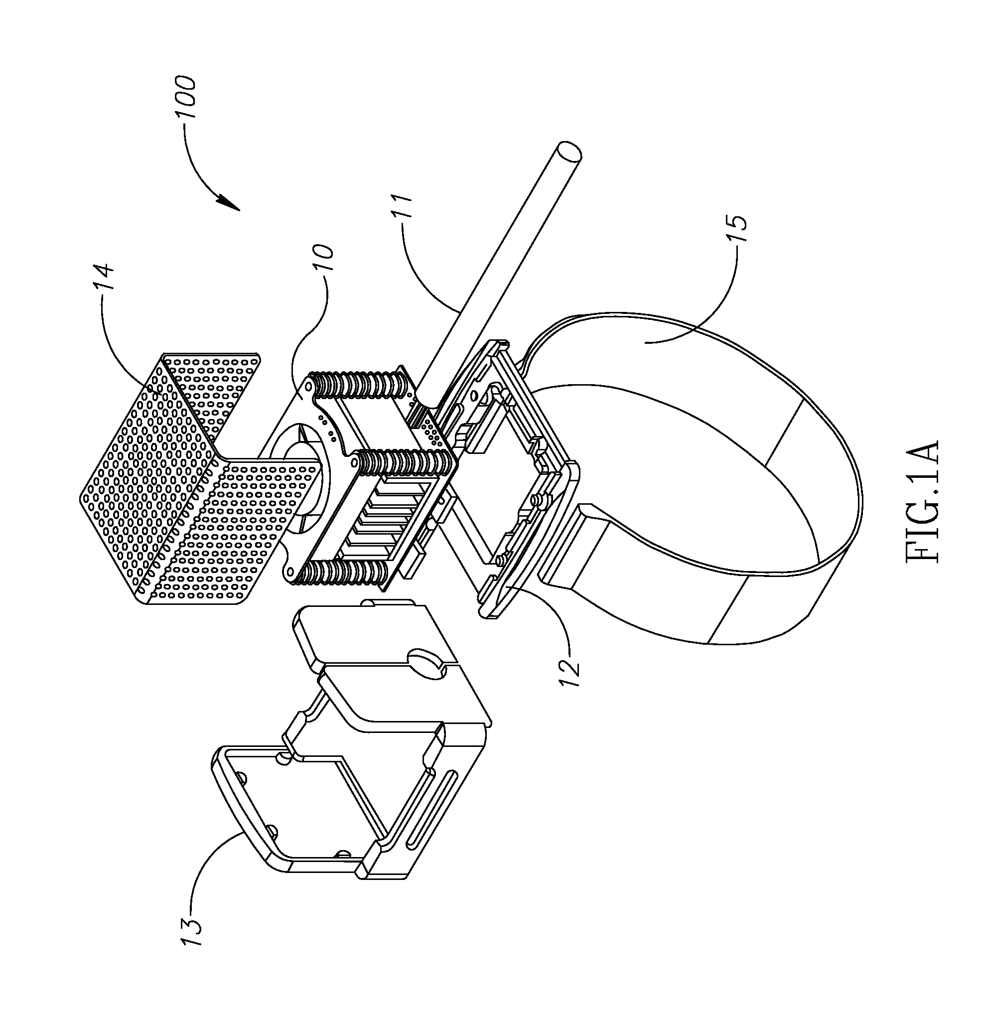
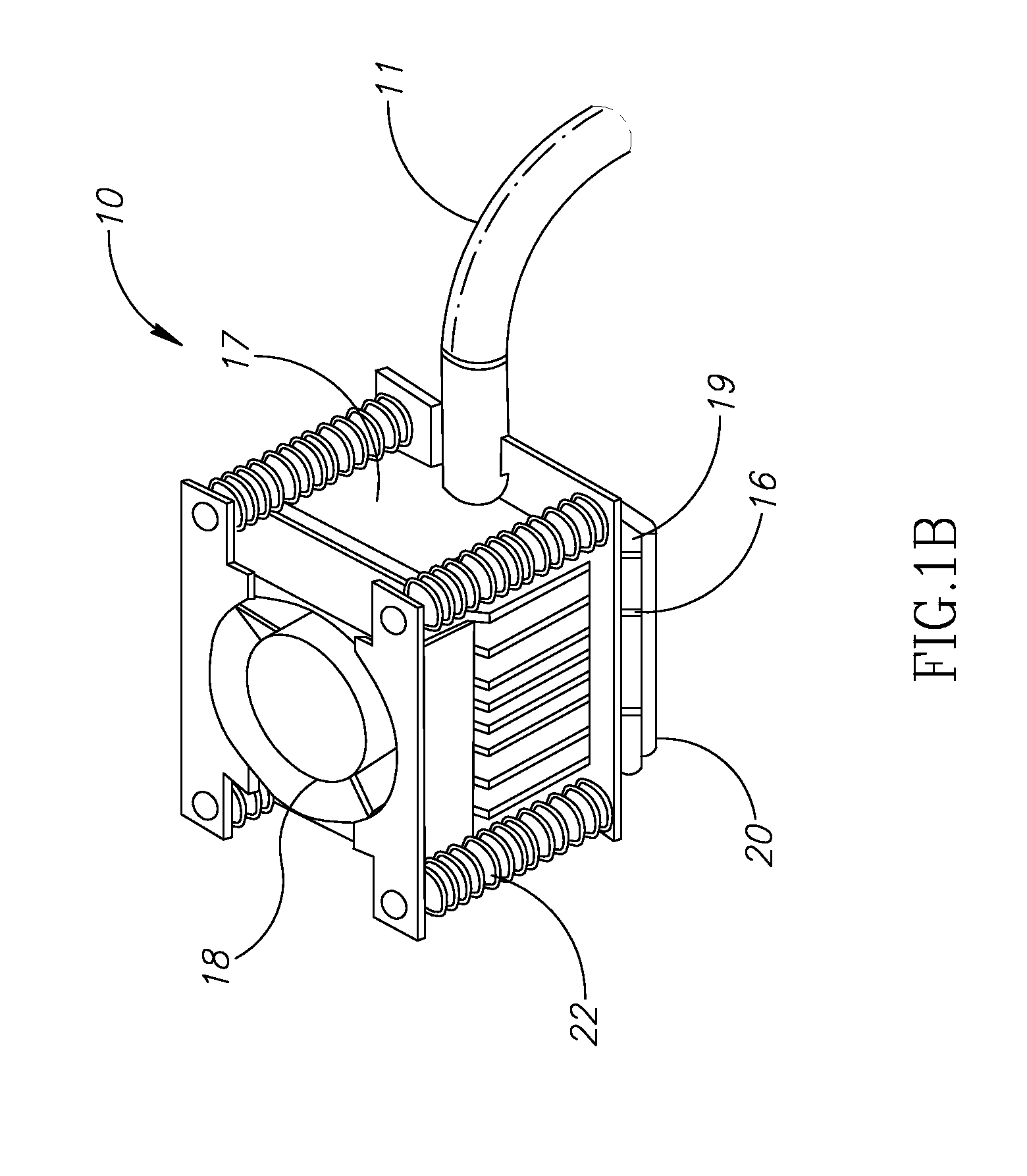
[0104]FIG. 1A shows an exploded view of a thermal stimulation probe 100, and FIG. 1B shows a view of the thermode unit 10, according to an exemplary embodiment. The thermal stimulation probe 100 delivers a thermal stimulus to a tested subject and comprises the following main components:

[0105]A thermoelectric cooler (TEC 19)

[0106]Temperature sensitive resistors (therm...


PUM


Abstract

A portable device for thermal stimulation of tissue of a patient comprising a heat control element having a proximal side and a distal side wherein a temperature difference can be generated between the proximal side and the distal side, and wherein the proximal side is capable of contacting the tissue. A fan capable of exchanging heat with surrounding air and a heat sink coupled to the distal side are provided. At least one resilient element connected between the heat sink and the fan is also provided, for supporting the fan so as to prevent direct contact between the heat sink and the fan. Furthermore at least one temperature sensor and circuitry are provided, wherein the circuitry activates the heat control element using the at least one temperature sensor, so as to achieve a desired temperature stimulation of the tissue at a rate of substantially 1 degree Celsius per second.

Description

FIELD OF THE INVENTION[0001]The present invention relates to an improved apparatus, system and method for thermal stimulation of tissue.BACKGROUND OF THE INVENTION[0002]The pain mediating system in a human consists of two kinds of afferent fibers: A-delta and C-fibers. These afferent pain fibers are characterized by different physiological parameters, for example, conduction velocity (5-30 m / s for A-delta fibers and 0.5-2 m / s for C-fibers). These two fiber types project to different parts of the dorsal horn of the spinal cord. In addition, stimulation of each kind of nociceptors evokes different type of sensation: A-delta fibers mediate first (sharp, pin-prick) pain sensation; C-fibers mediate the sensation of second pain usually perceived as burning sensation.[0003]Dysfunction of pain- and sensory-mediated systems often accompanies various neurological disorders as well as other pain syndromes of unknown etiology. Therefore, selective activation and identification of the response m...

Claims


Application Information

Patent Timeline
Patent Type & Authority Applications(United States)
IPC IPC(8): A61F7/00
CPCA61F2007/0075A61F7/007
Inventor BEN ASHER, HANANHAIMAN, AMIR
Owner MEDOC
Why Eureka
Try Eureka