
Thermoelectric conductivity measurement instrument of thermoelectric device and measuring method of the same

a technology of thermoelectric devices and measuring instruments, which is applied in the direction of instruments, heat measurement, force measurement, etc., can solve the problems of difficult separation and measurement, difficult to separate and measure, and almost impossible with current technology to simultaneously measure thermoelectric conductivity

Inactive Publication Date: 2015-05-14
ELECTRONICS & TELECOMM RES INST
View PDF15 Cites 9 Cited by
  • Summary
  • Abstract
  • Description
  • Claims
  • Application Information

AI Technical Summary

Benefits of technology

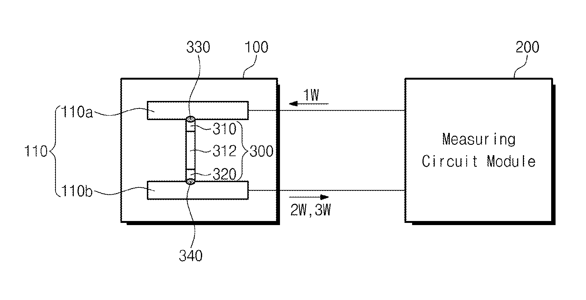
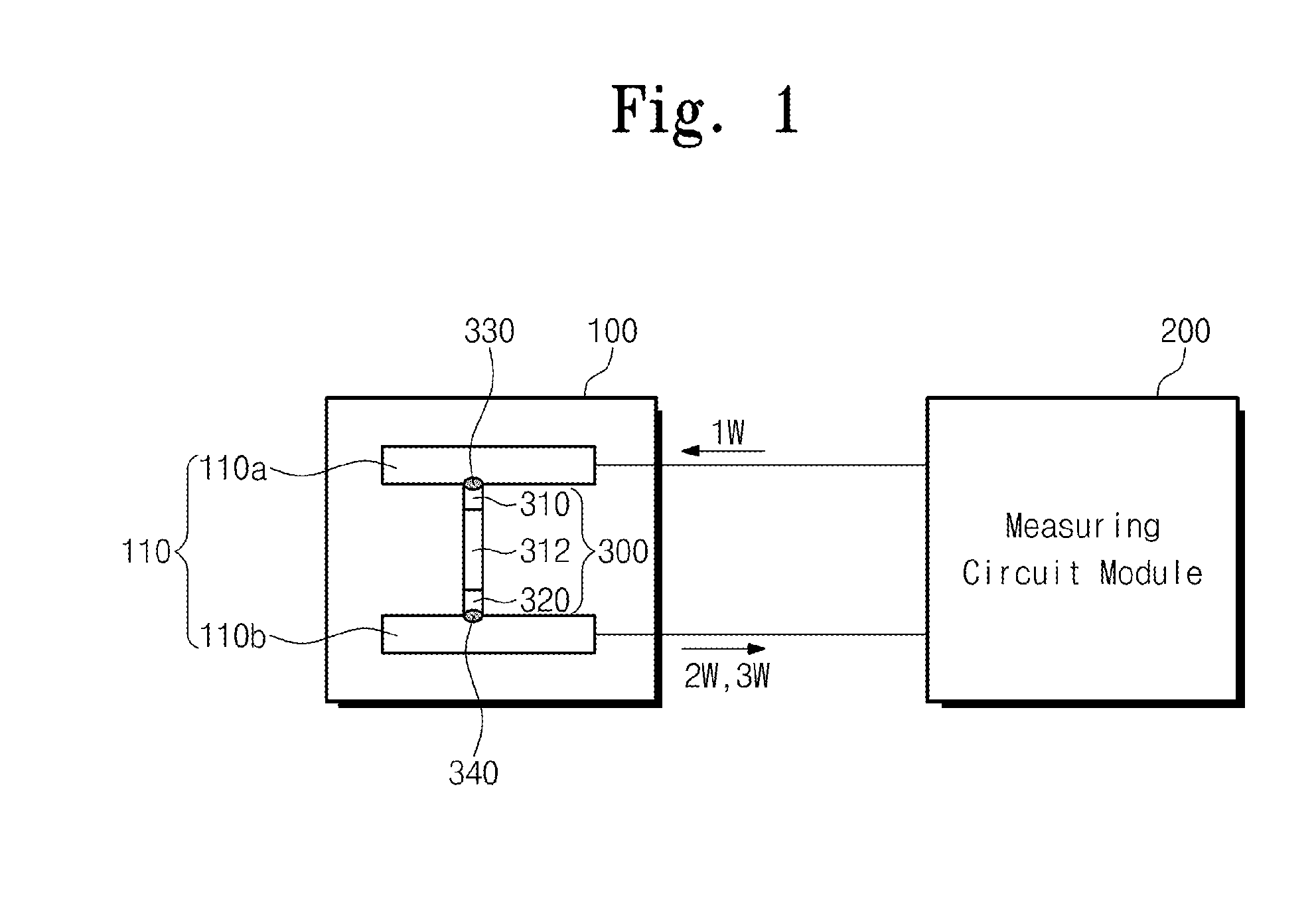
This patent describes a device that measures the temperature of a sample object using thermoelectric current. The device includes a circuit module that generates a source of AC voltage and provides it to the sample object. It also includes a differential amplifier that amplifies the thermoelectric current and a lock-in amplifier that removes noise and detects the second part of the thermoelectric current. The technical effects of this device are its ability to accurately measure the temperature of a sample object and to remove background noise from the measurements.

Problems solved by technology

However, it is almost impossible with a current technology to simultaneously measure the thermoelectric conductivity, while heating the contact point.
This is because it is difficult to separate and measure a weak thermoelectric voltage generated at the contact point between a plate electrode and a sample piece from a DC voltage needed to maintain a direct current, when using the direct current.
Further, the is also because it is difficult to separate and measure a driving voltage and the thermoelectric voltage, because a frequency of the driving voltage is the same as that of the thermoelectric voltage generated from temperature oscillation induced by the Paltier effect, even when using an alternating current.

Method used


Image

  • Thermoelectric conductivity measurement instrument of thermoelectric device and measuring method of the same
  • Thermoelectric conductivity measurement instrument of thermoelectric device and measuring method of the same
  • Thermoelectric conductivity measurement instrument of thermoelectric device and measuring method of the same

Examples


Embodiment Construction

[0034]Preferred Embodiments of the inventive concept will be described below in more detail with reference to the accompanying drawings. These and other advantages and characteristics of the present invention and methods achieving the same appear evident from the following description of preferred embodiments of the invention illustrated, as a non-limiting example, in the figures of the enclosed drawings. The present invention may, however, be embodied in different forms and should not be constructed as limited to the embodiments set forth herein. Rather, these embodiments are provided so that this disclosure will be thorough and complete, and will fully convey the scope of the present invention to those skilled in the art. In the drawings, the same components are designated by the same reference numerals over the entire specification.

[0035]The terms used herein are merely to describe a specific embodiment, and thus the present invention is not limited to them. Further, as far as si...


PUM

PropertyMeasurementUnit
thermoelectric conductivityaaaaaaaaaa
physical propertiesaaaaaaaaaa
thermoelectric AC voltageaaaaaaaaaa

Abstract

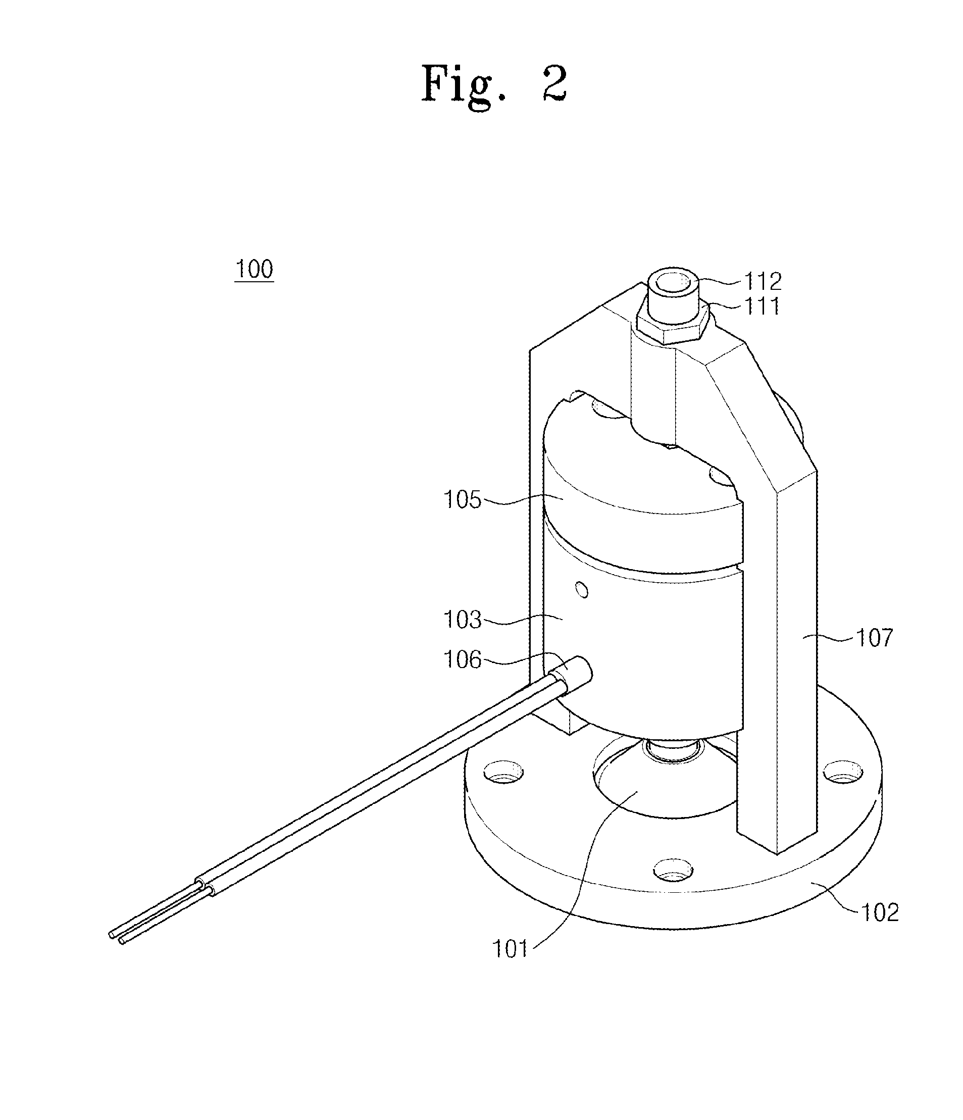
Provided are a thermoelectric conductivity measurement instrument of a thermoelectric device and a measuring method of the same. The thermoelectric conductivity measurement instrument of the thermoelectric device includes a sample piece fixing module configured to provide an environment for measuring physical properties of the thermoelectric device as a sample piece and comprising an electrode part configured to provide contact points which are respectively in contact with both ends of the sample piece, and a measuring circuit module configured to provide a source AC voltage of a first frequency heating the sample piece to the electrode part, detect a first thermoelectric AC voltage of a second frequency greater than the first frequency and a second thermoelectric AC voltage of a third frequency greater than the second frequency, which are generated by a temperature change occurring at the contact points, and then obtain the thermoelectric conductivity.

Description

CROSS-REFERENCE TO RELATED APPLICATIONS[0001]This U.S. non-provisional patent application claims priority under 35 U.S.C. §119 of Korean Patent Application No. 10-2013-0135482, filed on Nov. 8, 2013, the entire contents of which are hereby incorporated by reference.BACKGROUND OF THE INVENTION[0002]The present invention disclosed herein relates to a testing apparatus of an electric device and a testing method of the same, and more particularly, to a thermoelectric conductivity measurement instrument of a thermoelectric device and a measuring method of the same.[0003]Recently, due to the growing interest in clean energy, studies have been done on a thermoelectric device has been. The thermoelectric device serves to convert heat energy into electric energy, or reversely to apply the electric energy and generate a difference in temperature.[0004]A 2T value (thermoelectric figure of merit value) is used as an indicator estimating thermoelectric efficiency. A ZT value is in proportion to ...

Claims


Application Information

Patent Timeline
Patent Type & Authority Applications(United States)
IPC IPC(8): G01N27/00G01R1/02G01K13/00G01R19/00G01L1/00
CPCG01N27/002G01R19/00G01R1/02G01K13/00G01L1/00G01N27/18G01N25/18
Inventor JUN, DONG SUKJANG, MOON GYUCHOI, WON CHUL
Owner ELECTRONICS & TELECOMM RES INST
Learn More