Mask pattern generation method and optical image calculation method

a technology of optical image and pattern generation method, which is applied in the direction of microlithography exposure apparatus, printers, instruments, etc., can solve the problem of long calculation time and other problems

Active Publication Date: 2015-05-14
CANON KK
View PDF16 Cites 5 Cited by
  • Summary
  • Abstract
  • Description
  • Claims
  • Application Information

AI Technical Summary

Problems solved by technology

However, with the calculation methods using a transmission cross coefficient as described in Jap

Method used


Image

  • Mask pattern generation method and optical image calculation method
  • Mask pattern generation method and optical image calculation method
  • Mask pattern generation method and optical image calculation method

Examples


Embodiment Construction

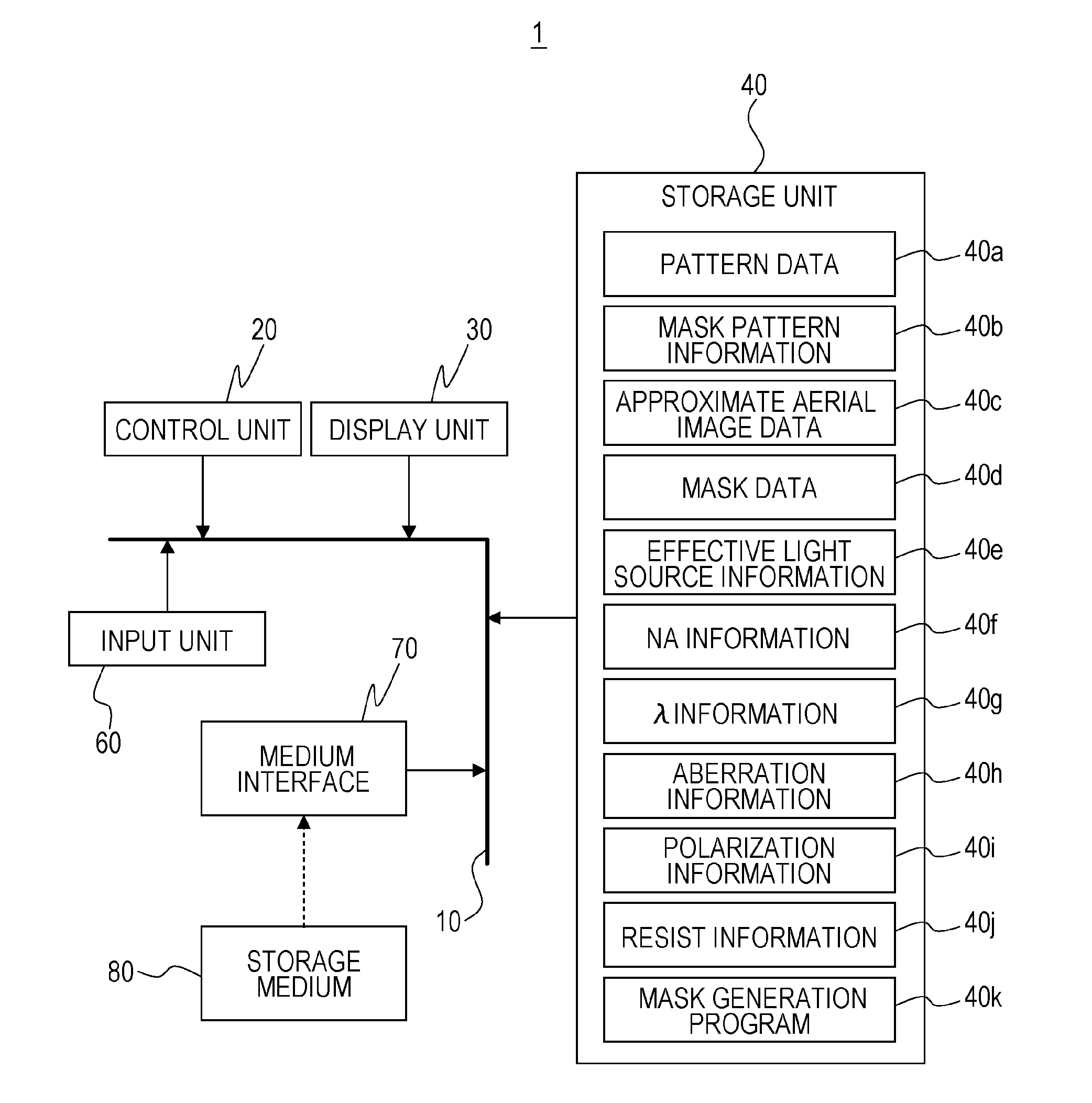
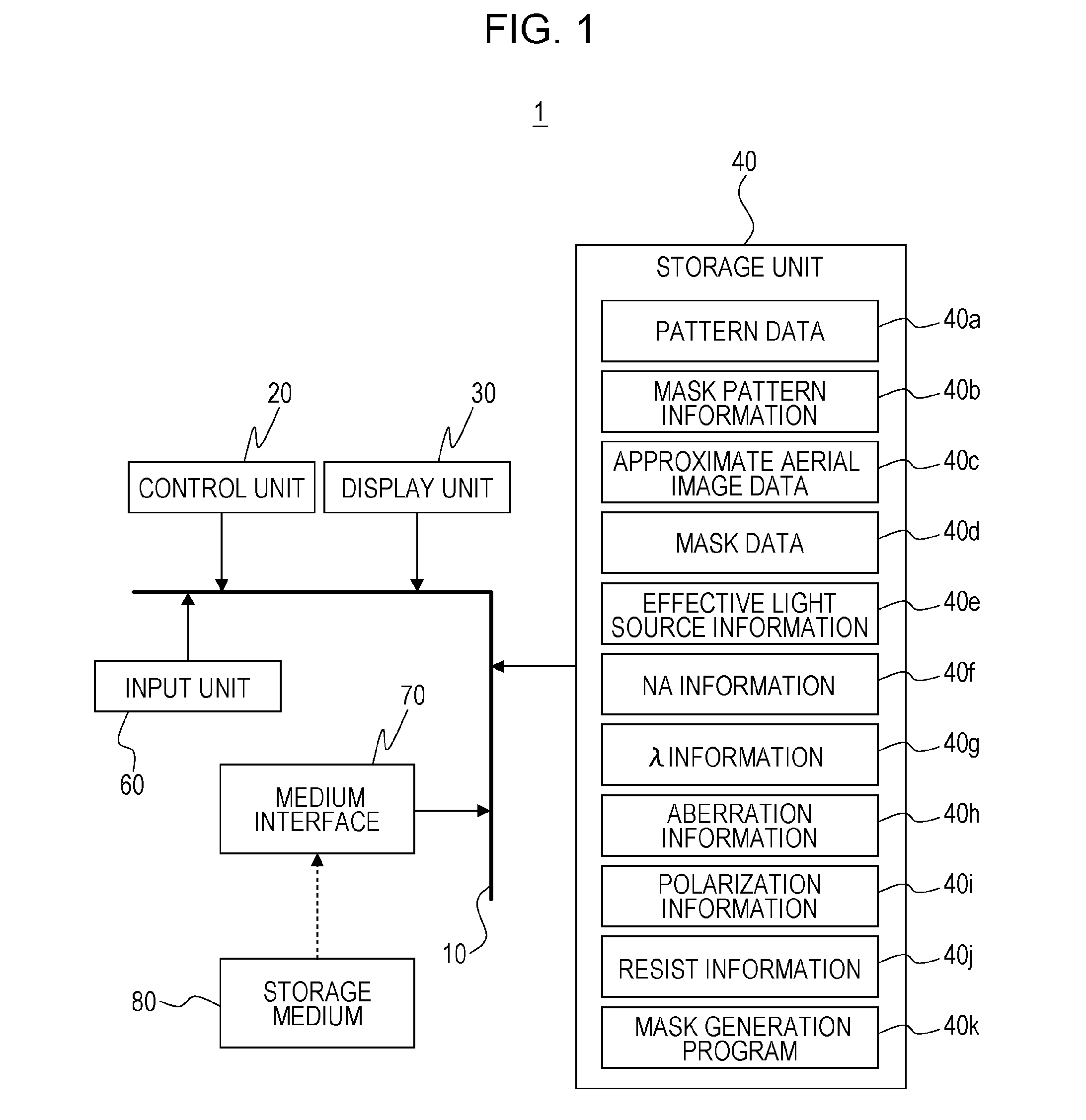
[0016]Various embodiments of the present invention will be described hereinafter with reference to the attached figures.

[0017]An embodiment is applicable to, for example, image formation calculation (partial coherent image formation calculation) of an optical system based on partial coherent image formation in an exposure apparatus or a microscope. The embodiment is also applicable to production of various devices, such as semiconductor chips including integrated circuits (ICs) and large-scale integrations (LSIs), display elements including liquid crystal panels, detection elements including magnetic heads, and imaging elements including charge-coupled devices (CCDs) and generation of data of a mask used in micro-mechatronics. Micro-mechatronics represents technologies in which mechanical systems on the order of microns having advanced features are fabricated by applying semiconductor integrated circuit fabrication techniques to microstructure fabrication, and such mechanical system...


PUM


Abstract

In a method for generating, with a computer, a pattern of a mask, a pattern on an object plane of a projection optical system is set, shifted plural pupil functions are generated, a matrix containing the generated plural pupil functions is defined, an image of the pattern on the object plane is calculated by generating a vector obtained by transposing and complex-conjugating a vector containing, as components, values of the pupil functions at origin coordinates on a pupil plane from among components of the matrix, and performing convolution integral between the pattern on the object plane and a Fourier transform of a product of the vector and the matrix, an assist pattern for the pattern on the object plane is generated using the calculated image, and a pattern of the mask including the pattern on the object plane and the assist pattern is generated.

Description

BACKGROUND OF THE INVENTION[0001]1. Field of the Invention[0002]The present invention relates to a mask pattern generation method and an optical image calculation method.[0003]2. Description of the Related Art[0004]In producing a semiconductor device using a photolithography technology, a projection exposure apparatus has been used which projects, through a projection optical system, a circuit pattern drawn on a mask (reticle) onto a substrate to transfer the circuit pattern to the substrate. In recent years, in accordance with miniaturization of semiconductor devices, a resolution enhancement technique to improve resolving power and depth of focus has been known.[0005]As such a resolution enhancement technique, there has been a method for disposing an assist pattern (assist feature) for assisting the resolution of a target pattern, as well as the target pattern to be formed on a substrate, on a mask.[0006]Japanese Patent Laid-Open Nos. 2004-221594 and 2008-40470 are typical example...

Claims


Application Information

Patent Timeline
IPC IPC(8): G03F7/20
CPCG03F7/70058G03F7/70616G03F1/70
Inventor YAMAZOE, KENJINAKAYAMA, RYOISHII, HIROYUKI
Owner CANON KK
Why Eureka
Try Eureka