Resistorless precharging

Active Publication Date: 2015-05-14
DELTA ELECTRONICS (THAILAND) PUBLIC CO LTD
View PDF1 Cites 31 Cited by
  • Summary
  • Abstract
  • Description
  • Claims
  • Application Information

AI Technical Summary

Benefits of technology

[0009]It is the object of the invention to provide a converter arrangement pertaining to the technical field initially mentioned, that enables a simpler design by reducing the design constraints. It is further object of the invention to provide such a converter arrangement with re

Problems solved by technology

In order to avoid high inrush currents, the input voltage may not directly be connected to the output capacitor, because the inductance of the boost inductor is quite small and therefore is not sufficient to limit the charge current sufficiently.
A main drawback of the prior art is that a resistor is needed to limit the charge current during the charging of the output capacitor.
For thermal reasons this resistor has to have a rather bu

Method used


Image

  • Resistorless precharging
  • Resistorless precharging
  • Resistorless precharging

Examples


Embodiment Construction

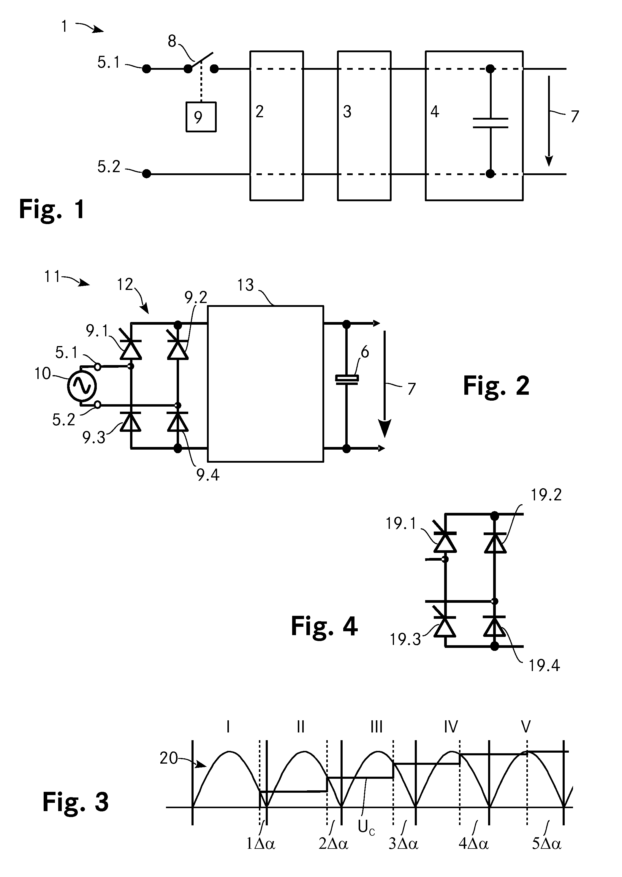
[0058]FIG. 1 shows a schematic depiction of a converter arrangement 1 according to the invention. The converter arrangement 1 includes two input terminals 5.1, 5.2 for connecting an AC input voltage, an input stage 2, a converter stage 3 and an output stage 4 that includes an output capacitor 6. A DC output voltage 7 is provided across the output capacitor 6.

[0059]The converter arrangement 1 further includes a controllable switch 8 that is controlled by a control unit 9. By properly controlling the controllable switch 8 during startup, i.e. by switching it ON during each half period for a certain amount of time, the charge current flowing through the output capacitor 6 can be controlled to be rather small such that the inrush current is limited to a level that does not damage the converter arrangement 1.

[0060]FIG. 2 shows another embodiment of the invention. The converter arrangement 11 includes a full-bridge rectifier 12 connected to the input terminals 5.1, 5.2 where a voltage sou...


PUM


Abstract

A boost PFC converter includes a rectifier, a converter and an output stage comprising an output capacitor where the DC output voltage is provided across the output capacitor. The rectifier includes four rectifying elements connected in a full bridge configuration where the upper two of these four rectifying elements are thyristors and where the lower two are diodes. In that the thyristors are controlled such as to be open for only a part of each half period of the input voltage, the amount of current per half period that is passed to the output capacitor is controllable and can be made very small. Accordingly, the charge current for precharging the output capacitor can be controllably limited such that a bulky precharge resistor is not required anymore to avoid high inrush currents.

Description

TECHNICAL FIELD[0001]The invention relates to converter arrangements including an input stage comprising two input terminals for connecting an AC input voltage, a converter stage for converting the AC input voltage to a DC output voltage and an output stage comprising an output capacitance, where the DC output voltage is provided across the output capacitance, the converter arrangement further including a controllable switch arranged in a current path from one of the two input terminals to the other and including said output capacitance and a control unit adapted to control the controllable switch for precharging the output capacitance at a startup of the converter arrangement. The invention further relates to a corresponding method for precharging an output capacitance of a converter arrangement and an automotive vehicle including at least one electric motor, a first energy storage for driving said at least one electric motor and including such a converter arrangement for charging ...

Claims


Application Information

Patent Timeline
IPC IPC(8): H02M1/42H02M7/12
CPCH02M7/12H02M1/42H02M1/4225H02M7/125H02M1/4233H02M1/36H02M1/32H02M1/0085Y02B70/10H02M1/081H02M7/145
Inventor HUFNAGEL, MICHAELSCHAFMEISTER, FRANK
Owner DELTA ELECTRONICS (THAILAND) PUBLIC CO LTD
Why Eureka
Try Eureka