
Steam flow rate metering device and metering method therefor

a flow rate metering and steam thermal value technology, applied in the field of inline metering, can solve the problems of large metering error, inability to accurately measure injected steam, and difficulty for conventional single-phase meters to reflect in real time such variations

Inactive Publication Date: 2015-05-14
CHEN JIGE +3
View PDF2 Cites 16 Cited by
  • Summary
  • Abstract
  • Description
  • Claims
  • Application Information

AI Technical Summary

Benefits of technology

This patent describes a new way to measure the flow of steam in real-time using a single energy gamma ray sensor and a venturi. This combined device can measure the ratio of saturated steam to saturated water, which is important for calculating the total mass flow and thermal value of the steam. This method also takes into account the potential phase velocity difference between the two phases, resulting in more accurate measurements. Overall, the device provides a novel way to measure steam flow rate and the related thermal value in real-time on an online basis.

Problems solved by technology

However, since injected steam has a specialty of high temperature, high pressure and vapor-liquid entrainment, there are many difficulties in accurately metering its flow rate, and thus the accurate metering of injected steam is a problem in the field of flow rate metering for a long time.
If the metering meter cannot track such variation, a larger metering error will be necessarily produced.
Thus, it is difficult to conventional single-phase meters to reflect in real time such variations, let alone to accurately meter the “saturated steam” and “saturated water” in real time, respectively.

Method used


Image

  • Steam flow rate metering device and metering method therefor
  • Steam flow rate metering device and metering method therefor
  • Steam flow rate metering device and metering method therefor

Examples


first embodiment

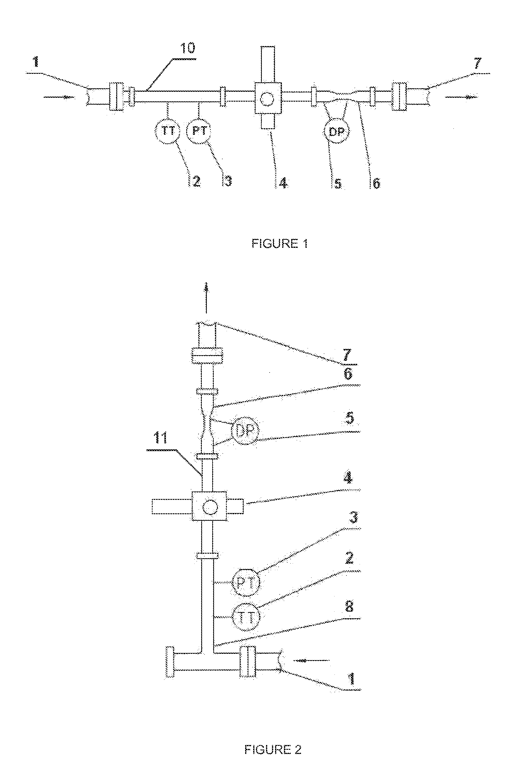
[0027]As shown in FIG. 1, the steam flow rate metering device of the invention is in a horizontally-arranged structure. The device comprises a pipeline. An inlet connection flange 1 is mounted to the inlet of the pipeline, and following the inlet connection flange 1, a temperature transmitter 2 and a pressure transmitter 3 are mounted to the pipeline successively. The device is characterized in that said pipeline is a horizontal pipeline 10, and following the pressure transmitter 3, a venturi 6 is mounted to the horizontal pipeline 10; a single energy gamma ray sensor 4 is arranged at the upstream of the inlet of the venturi 6 or at the throat portion of the venturi 6; a differential pressure transmitter 5 is mounted to the venturi so as to measure in real time the differential pressure value produced when a fluid flows through the venturi; an outlet of said pipeline 7 follows the venturi 6.

[0028]The working process is as follow: steam fluid enters the steam meter through the inlet ...

second embodiment

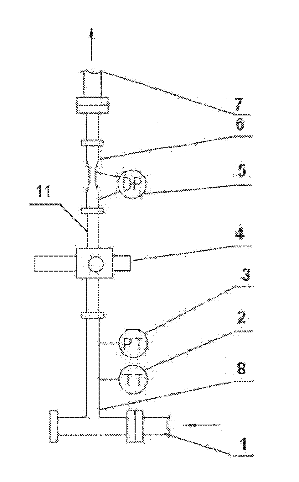
[0029]As shown in FIG. 2, the steam flow rate metering device of the invention is in a vertically-arranged structure. The device comprises a vertical pipeline 11. An inlet connection flange 1 is mounted to the inlet of the pipeline, and following the inlet connection flange 1, an inlet blind three-way means 8 is mounted to the vertical pipeline. A temperature transmitter 2 and a pressure transmitter 3 are mounted to said inlet blind three-way means 8 successively. Following the pressure transmitter 3, a venturi 6 is mounted to said pipeline. A single energy gamma ray sensor 4 is arranged at the upstream of the inlet of the venturi 6 or at the throat portion of the venturi 6. A differential pressure transmitter 5 is mounted to the venturi 6 so as to measure in real time the differential pressure value produced when a fluid flows through the venturi. An outlet of said pipeline 7 follows the venturi 6.

[0030]The working process is as follow: steam fluid enters the steam meter through th...

third embodiment

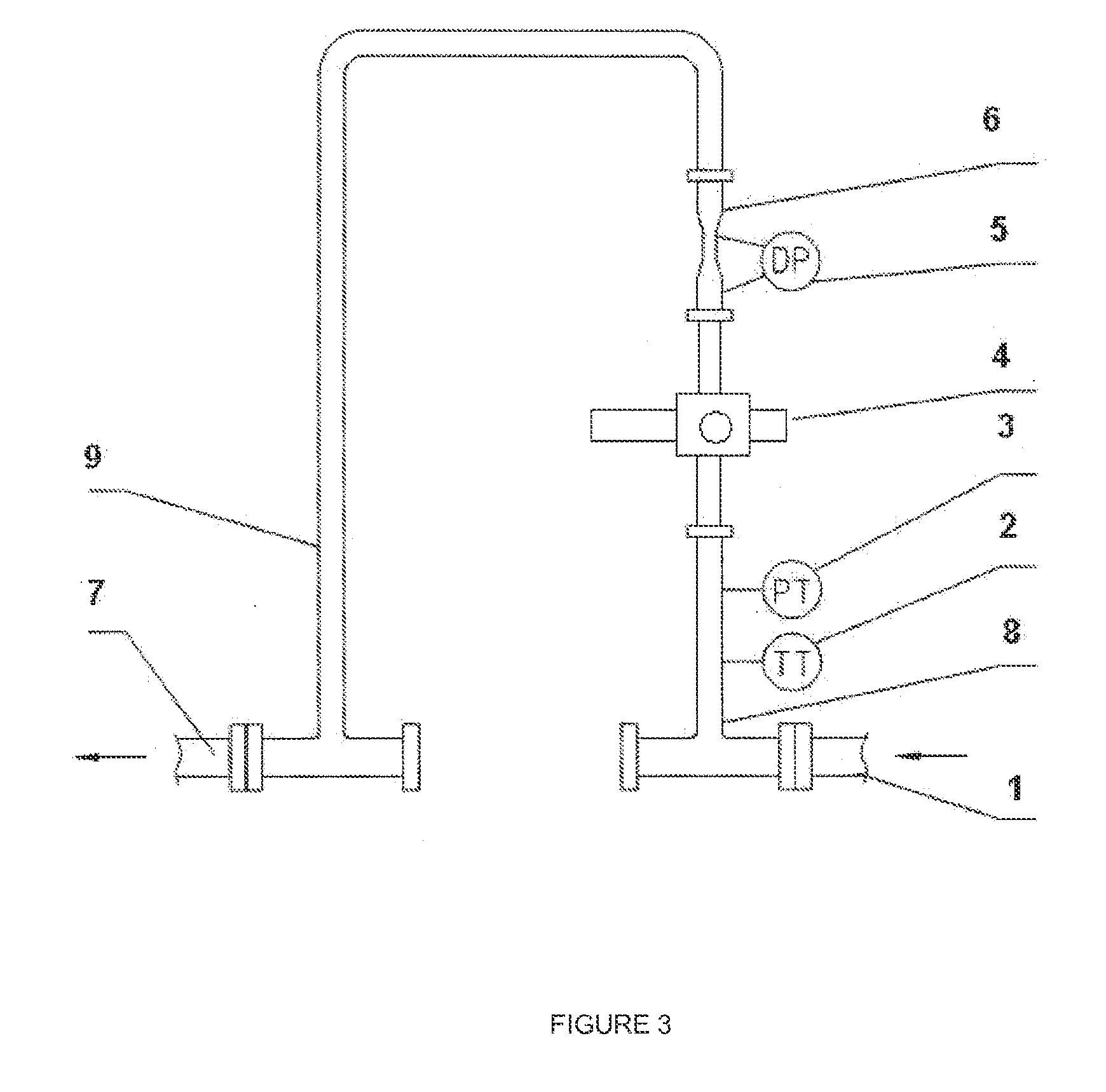
[0031]FIG. 3 shows the steam flow rate metering device of the invention, which is in an inverted U-shape skid pipeline. The device comprises an inverted U-shape pipeline 9. An inlet connection flange 1 is mounted to the inlet of the inverted U-shape pipeline, and following the inlet connection flange 1, an inlet blind three-way means 8 is mounted to the said pipeline. A temperature transmitter 2 and a pressure transmitter 3 are mounted to the inlet blind three-way means 8 successively. Following the pressure transmitter 3, a venturi 6 is mounted to the pipeline. A single energy gamma ray sensor 4 is arranged at the upstream of the inlet of the venturi 6 or at the throat portion of the venturi 6. A differential pressure transmitter is mounted to the venturi so as to measure in real time the differential pressure value produced when a fluid flows through the venturi. An outlet of said pipeline 7 follows the venturi 6.

[0032]The working process is as follow: steam fluid enters the steam...


PUM

PropertyMeasurementUnit
temperatureaaaaaaaaaa
differential pressureaaaaaaaaaa
steam flow rate meteringaaaaaaaaaa

Abstract

Provided are a steam flow metering device and a metering method therefor. The device mainly comprises a mono-energetic gamma sensor (5), a Venturi-type flowmeter (6), a temperature transmitter (2), a pressure transmitter (3), a pipe connection section at the steam-inlet (1), and a pipe connection section at the steam-outlet (7), the function thereof being to measure the quantity of saturated water and saturated steam within the steam effectively and in real time. The measuring method thereof is: measuring the dryness of the saturated steam at the cross section by the mono-energetic gamma sensor (5); measuring the mass flow of the total steam by the Venturi-type flowmeter (6), and at the same time considering the potential slip (the phase velocity difference) existing in the saturated steam and the saturated water, such that the quantity of saturated steam, the quantity of saturated water and the corresponding thermal values thereof can be calculated in real time by a computer system by utilizing the method of analytical solution to the vapour / liquid annular flow slip. The vapour and the liquid phases in the steam can be directly distinguished and measured by the present measuring method. The present method is different from the conventional method of single-phase metering encryption correction, has no additional error, there is no influence from the type of flow and the phase change between the vapour and liquid, and has a higher measuring precision.

Description

FIELD OF THE INVENTION[0001]The invention relates to the inline metering field of steam flow rate and steam thermal value, particularly, to a steam flow rate metering device which can meter real time steam injected to drive heavy oil during the oil field production process. The present invention further relates to a method for metering steam flow rate by using such metering device.DESCRIPTION OF THE PRIOR ART[0002]Steam is an important secondary energy source in the petrochemical plant. In view of enterprise benefit, the consumption of steam should be reduced in order to reduce production costs. In view of saving energy and reducing consumption, a basic problem which should be solved is the energy metering, and during the heavy oil production process driven by steam in oil field, only when injected steam is accurately metered, the quantitative objective of saving energy can be determined. Recently, domestic heavy oil resources are continuously explored and developed, and more than 9...

Claims


Application Information

Patent Timeline
Patent Type & Authority Applications(United States)
IPC IPC(8): G01F1/88G01T1/16G01N23/00G01F1/44
CPCG01F1/88G01N23/00G01T1/16G01F1/44G01F1/74G01N23/12G01F1/36G01F1/363
Inventor CHEN, JIGEPAN, YANZHIWU, GUODONGWU, ZHIYONG
Owner CHEN JIGE
Learn More