Sensor arrangement and method for generating an amplified sensor signal

a technology of amplified sensor and array, which is applied in the direction of electrical testing, semiconductor electrostatic transducers, instruments, etc., can solve problems such as signal attenuation, and achieve the effect of cost-effectiveness

Active Publication Date: 2015-05-21
AMS AG
View PDF9 Cites 38 Cited by
  • Summary
  • Abstract
  • Description
  • Claims
  • Application Information

AI Technical Summary

Benefits of technology

[0030]It is an advantage that a cost effective circuit with a small number of components is sufficient for

Problems solved by technology

The circuit shows parasitic capacitor

Method used


Image

  • Sensor arrangement and method for generating an amplified sensor signal
  • Sensor arrangement and method for generating an amplified sensor signal
  • Sensor arrangement and method for generating an amplified sensor signal

Examples


Embodiment Construction

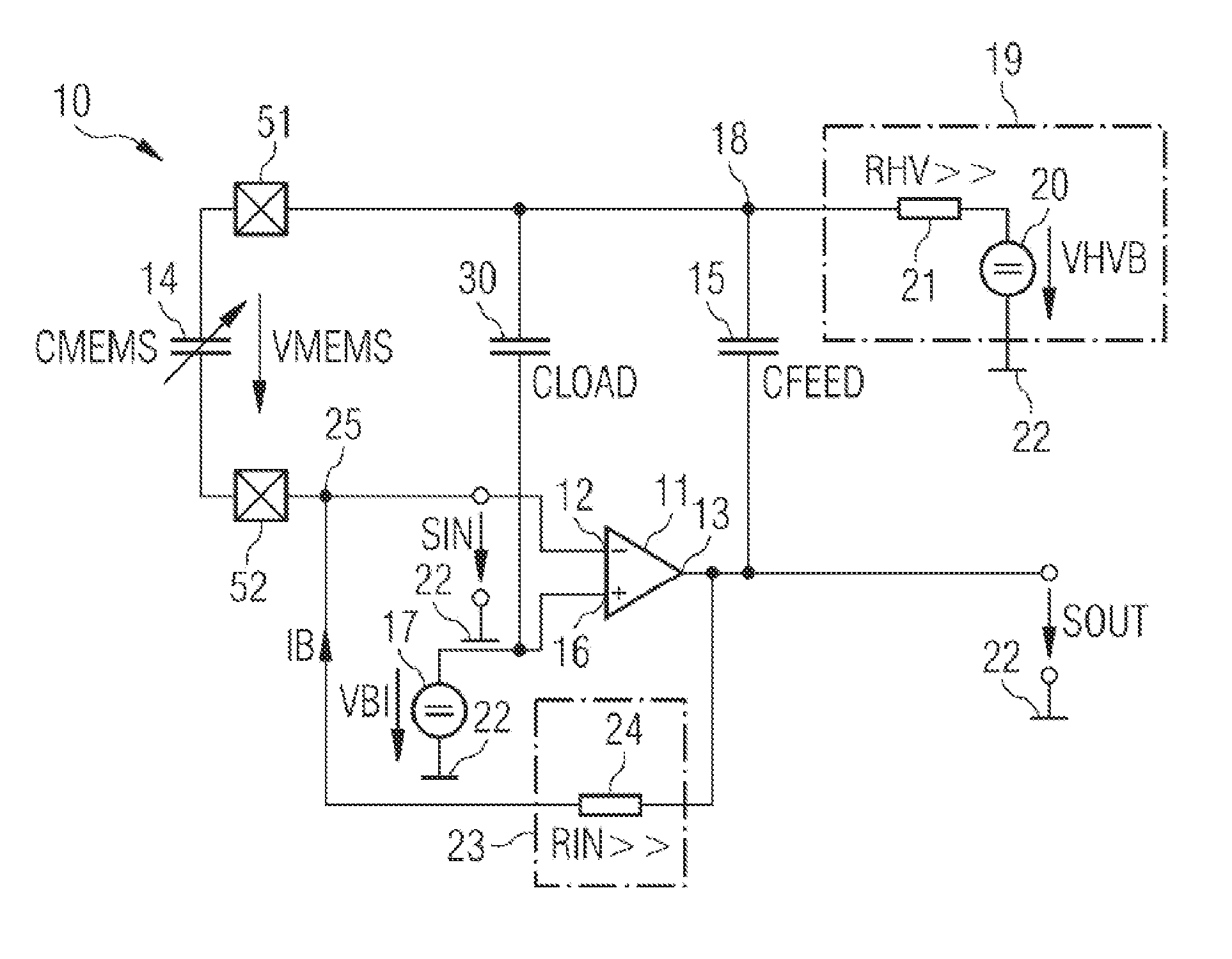
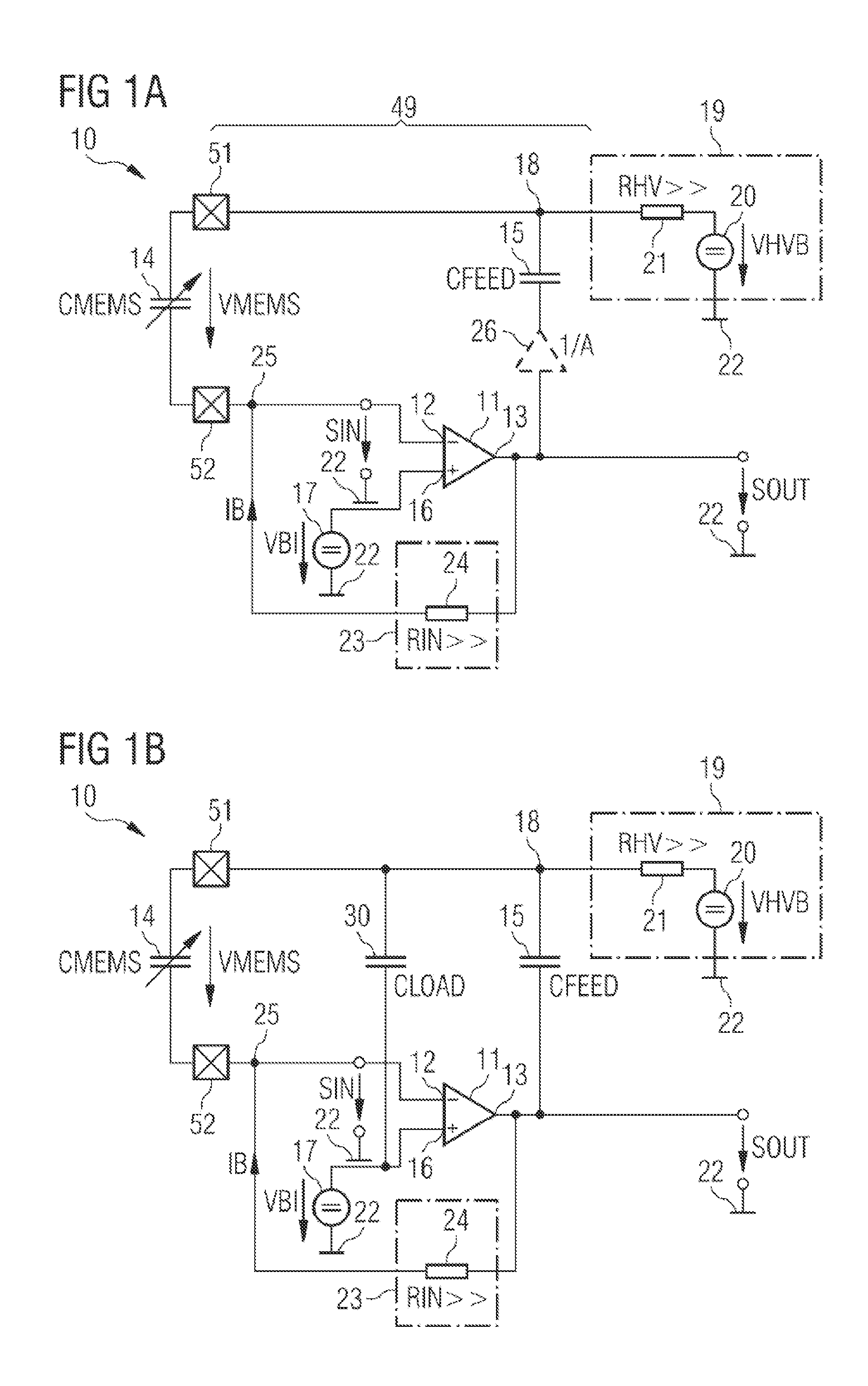
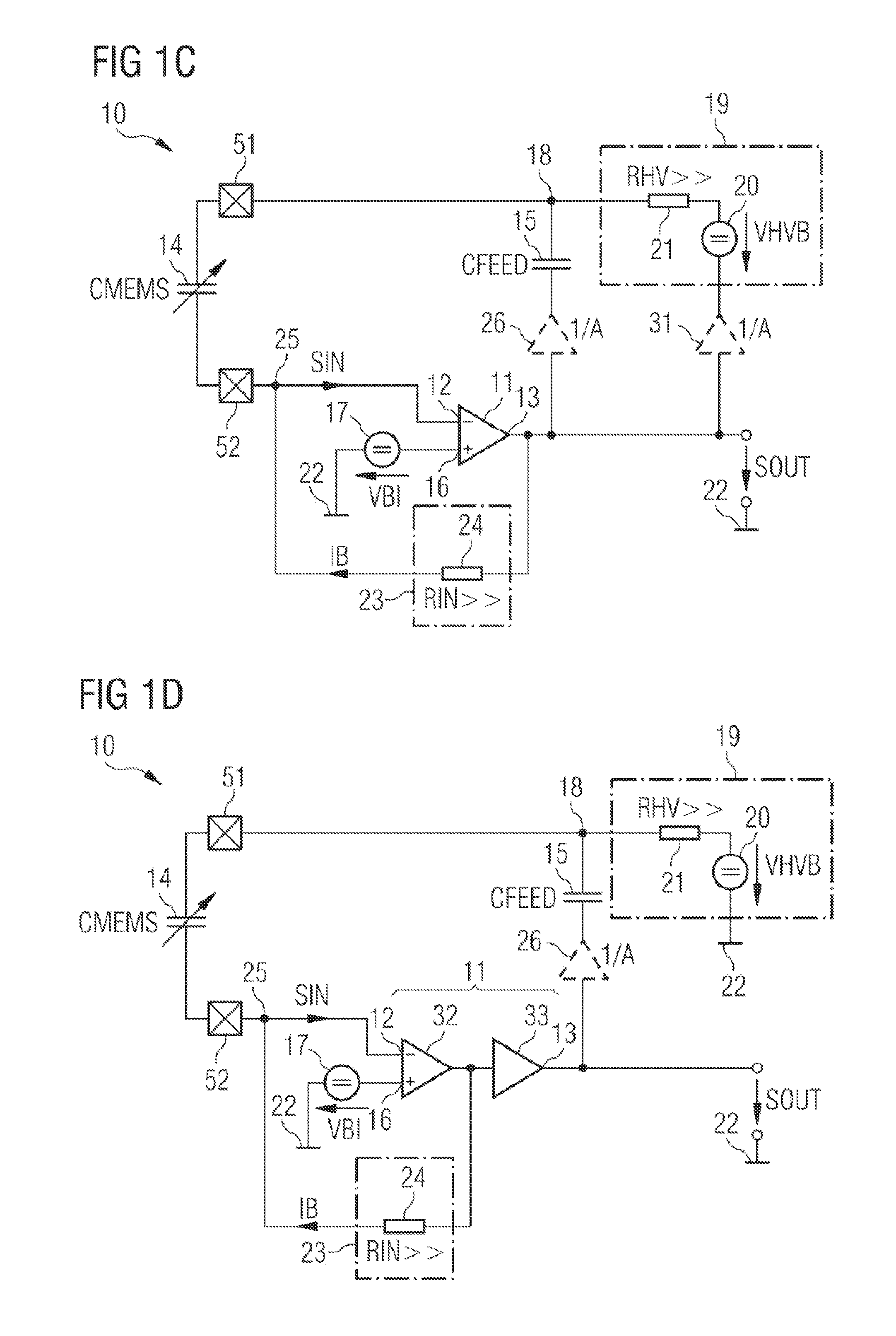
[0035]FIG. 1A shows an exemplary embodiment of a sensor arrangement 10. The sensor arrangement 10 comprises an amplifier 11 having a signal input 12 and a signal output 13. Moreover, the sensor arrangement 10 comprises a feedback path with a capacitive sensor 14 and a feedback capacitor 15. The capacitive sensor 14 and the feedback capacitor 15 are arranged in series between the signal output 13 and the signal input 12. The capacitive sensor 14 is directly connected to the signal input 12, whereas the feedback capacitor 15 is connected to the signal output 13. The capacitive sensor 14 may be realized as a capacitive microphone. For instance, the capacitive sensor 14 is implemented as a micro-electro-mechanical-system microphone, abbreviated to MEMS microphone. The capacitive sensor 14 typically has a capacitance value CMEMS that is variable and obtains a very small nominal value. The feedback capacitor 15 has a capacitance value CFEED that is constant. Furthermore, the amplifier 11 ...


PUM


Abstract

A sensor arrangement (10) comprises an amplifier (11) having a signal input (12) to receive an input signal (SIN) and a signal output (13) to provide an amplified sensor signal (SOUT) that is an inverted signal with respect to the input signal (SIN). Furthermore, the sensor arrangement (10) comprises a feedback path connecting the signal output (13) to the signal input (12), wherein the feedback path comprises a series connection of a capacitive sensor (14) and a feedback capacitor (15). A voltage source arrangement (19) of the sensor arrangement (10) is connected to a feedback node (18) between the capacitive sensor (14) and the feedback capacitor (15).

Description

CROSS-REFERENCE TO RELATED APPLICATION[0001]This application is a continuation application of PCT / EP2013 / 059732, filed on May 10, 2013, which is hereby incorporated by reference in its entirety for all purposes.FIELD OF THE INVENTION[0002]The invention refers to a sensor arrangement and to a method for providing an amplified sensor signal.BACKGROUND OF THE INVENTION[0003]A sensor arrangement typically comprises a sensor. The sensor can be of the capacitive type. The quantity that is to be measured changes the capacitance value of the capacitive sensor. The sensor arrangement is foreseen for generating an amplified sensor signal that depends on the capacitance value of the capacitive sensor.[0004]An example for the capacitive sensor is a microphone. The microphone can be realized as a micromechanical microphone.[0005]Publication “A 828 μW 1.8V 80 dB Dynamic-Range Readout Interface for a MEMS Capacitive Microphone”, S. A. Jawed et al., 34th European Solid-State Circuits Conference, Se...

Claims


Application Information

Patent Timeline
IPC IPC(8): G01R27/26G01R1/30
CPCG01R1/30G01R27/2605H03F1/34H04R19/04H04R19/005
Inventor STEINER, MATTHIAS
Owner AMS AG
Why Eureka
Try Eureka