
Microphone and microphone device

Active Publication Date: 2015-05-21
AUDIO-TECHNICA
View PDF10 Cites 3 Cited by
  • Summary
  • Abstract
  • Description
  • Claims
  • Application Information

AI Technical Summary

Benefits of technology

The invention allows for a large dynamic range of output signals without increasing the output impedance at different frequencies. This is useful in improving the quality of output signals and ensuring better performance of electronic devices.

Problems solved by technology

Unfortunately, such a reduction in input impedance of the high-pass filter 30 leads to distortion of output signals from the impedance converter 2.
In the output amplifier 4, however, a noise level increases due to the high output impedance of the high-pass filter 30.

Method used


Image

  • Microphone and microphone device
  • Microphone and microphone device
  • Microphone and microphone device

Examples


Embodiment Construction

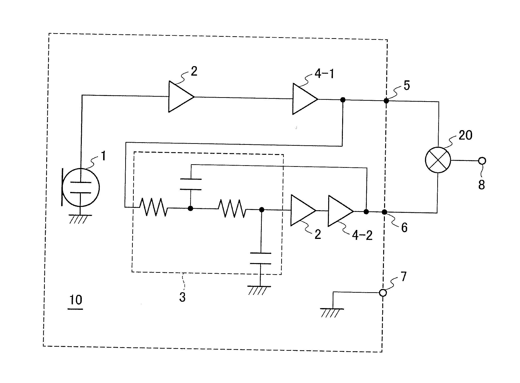
[0028]Embodiments of a microphone and a microphone device according to the present invention will now be described with reference to the accompanying drawings. FIG. 1 is a circuit diagram illustrating an example configuration of a microphone 10 according to the embodiment. As shown in FIG. 1, the microphone 10 includes a microphone unit 1, an impedance converter 2 disposed at a subsequent stage of the microphone unit 1, a low-pass filter circuit 3, and an output amplifier 4-1 and an output amplifier 4-2. The microphone unit 1, for example, is a condenser microphone unit.

[0029]The output from the microphone 10 is a balanced output. The output terminal is therefore a three-pin terminal including a HOT terminal 5, a COLD terminal 6, and a ground terminal 7. The impedance converter 2 and the output amplifier 4-1 are connected in series between the output terminal of the microphone unit 1 and the HOT terminal 5. The impedance converter 2, the output amplifier 4-1, the low-pass filter cir...


PUM


Abstract

A microphone comprises a microphone unit; and a HOT terminal and a COLD terminal that produce a balanced output of output signals of the microphone unit, and no filter circuit is disposed between the microphone unit and the HOT terminal and a low-pass filter is disposed only between the microphone unit and the COLD terminal.

Description

TECHNICAL FIELD [0001]The present invention relates to a microphone and a microphone device.BACKGROUND ART [0002]Outputs from a microphone (in particular, a condenser microphone) sometimes include wind noise and / or vibration noise. In order to reduce the noise, a filter circuit is disposed in a preceding stage of an output circuit of the microphone. Since the wind noise and vibration noise are mainly composed of low frequency components, the filter circuit used is a high-pass filter (a low-cut filter).[0003]A condenser microphone has high output impedance. Thus, an impedance converter is provided on the output side of the condenser microphone to reduce the output impedance. The impedance converter mainly includes a field-effect transistor (FET). The high-pass filter that attenuates the low frequency components is disposed in a subsequent stage of the impedance converter and in a preceding stage of the output circuit of the microphone (refer to PTL 1, Japanese Unexamined Patent Appli...

Claims


Application Information

Patent Timeline
IPC IPC(8): H04R1/04
CPCH04R1/04H04R19/00
Inventor AKINO, HIROSHI
Owner AUDIO-TECHNICA
Features
  • Generate Ideas
  • Intellectual Property
  • Life Sciences
  • Materials
  • Tech Scout
  • Unparalleled Data Quality
  • Higher Quality Content
  • 60% Fewer Hallucinations
Learn More