Storage structure of an electrical energy storage cell

a technology of electrical energy storage and storage structure, which is applied in the direction of hybrid cell details, cell components, electrochemical generators, etc., can solve problems such as failure of batteries, and achieve the effect of high long-term stability

Active Publication Date: 2015-05-21
SIEMENS AG
View PDF2 Cites 0 Cited by
  • Summary
  • Abstract
  • Description
  • Claims
  • Application Information

AI Technical Summary

Benefits of technology

[0004]It is an object of the invention to provide a storage cell of an electrical energy storage means, which has a higher long-term stability compared to the prior art and withstands a higher number of cycles of charging and discharging operations.
[0010]Such a narrow distribution structure of the particles of the active storage material with the given d50 thus has the effect that the particles are large enough that they do not have a tendency to elevated sintering, like the nanoparticles; secondly, the mean value of the particles is sufficiently small that the active surface area of the individual grains of the active storage material is sufficiently high that the corresponding chemical processes, especially redox processes, proceed very rapidly, which advantageously shortens the cycle times of the energy storage cell and increases the performance of the storage cell. In addition, any adverse effects that are caused by raw material or process contamination can be minimized by the high active surface area of the grains of the active storage material.
[0011]For even better stabilization of the storage structure against sintering over several cycles of a chemical process in the storage cell, especially of the redox process, it is appropriate also to introduce an inert material in divided form into the raw materials of the active storage material, in which case this inner material is present in the storage structure in finely divided form between the grains of the active storage material. Such an inert material likewise has a maximum grain size of 10 μm, especially of 3 μm. Such an inert material acts as a support structure which additionally further reduces the sintering tendency of the storage material. The proportion by volume of the inert material in the storage material here is advantageously less than 50%, especially between 5% and 15%.
[0015]The shape of the grains of the active storage material is advantageously aspherical. In this context, the grains may preferably be in oblate, prolate, platelet-shaped, acicular or tubular form, because such an aspherical, i.e. non-ball-shaped, particle morphology increases the surface to volume ratio of the particles.

Problems solved by technology

This leads to aging and subsequently to failure of the battery.

Method used


Image

  • Storage structure of an electrical energy storage cell
  • Storage structure of an electrical energy storage cell
  • Storage structure of an electrical energy storage cell

Examples


Embodiment Construction

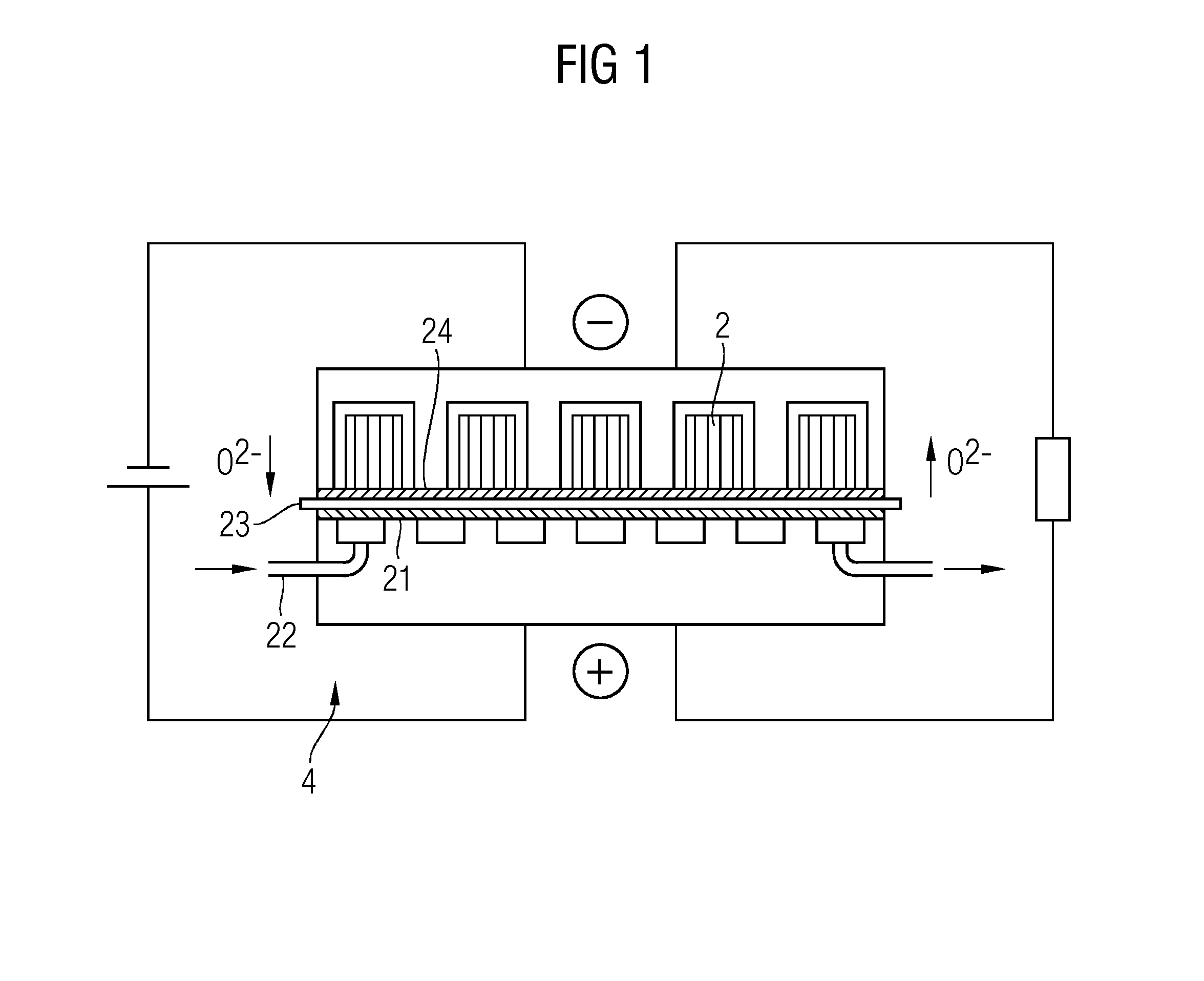
[0023]With reference to FIG. 1, there will first of all be a description, in schematic form, of the way in which a rechargeable oxide battery (ROB) works, to the extent necessary for the present description of the invention. A standard setup of an ROB involves blowing in a process gas, especially air, via a gas supply 18 at a positive electrode 21, which is also referred to as air electrode, with removal of oxygen from the air. The oxygen passes in the form of oxygen ions O2− through a solid electrolyte 23 that adjoins the positive electrode to a negative electrode 24, which is also referred to as storage electrode. If an impervious layer of the active storage material were thus to be present on the negative electrode 24, i.e. on the storage electrode, the storage capacity of the battery would thus rapidly be exhausted.

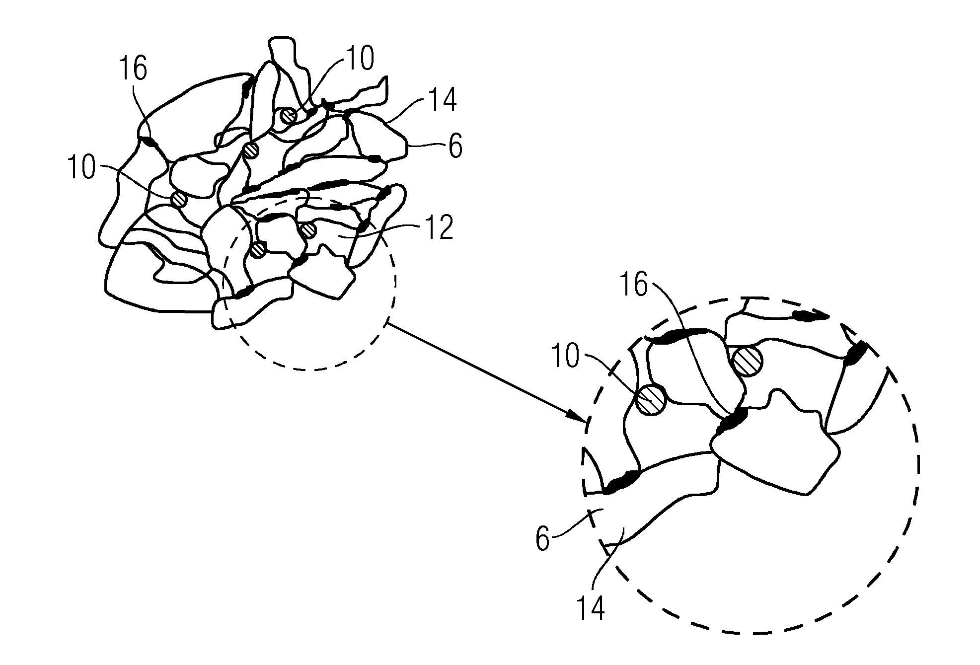
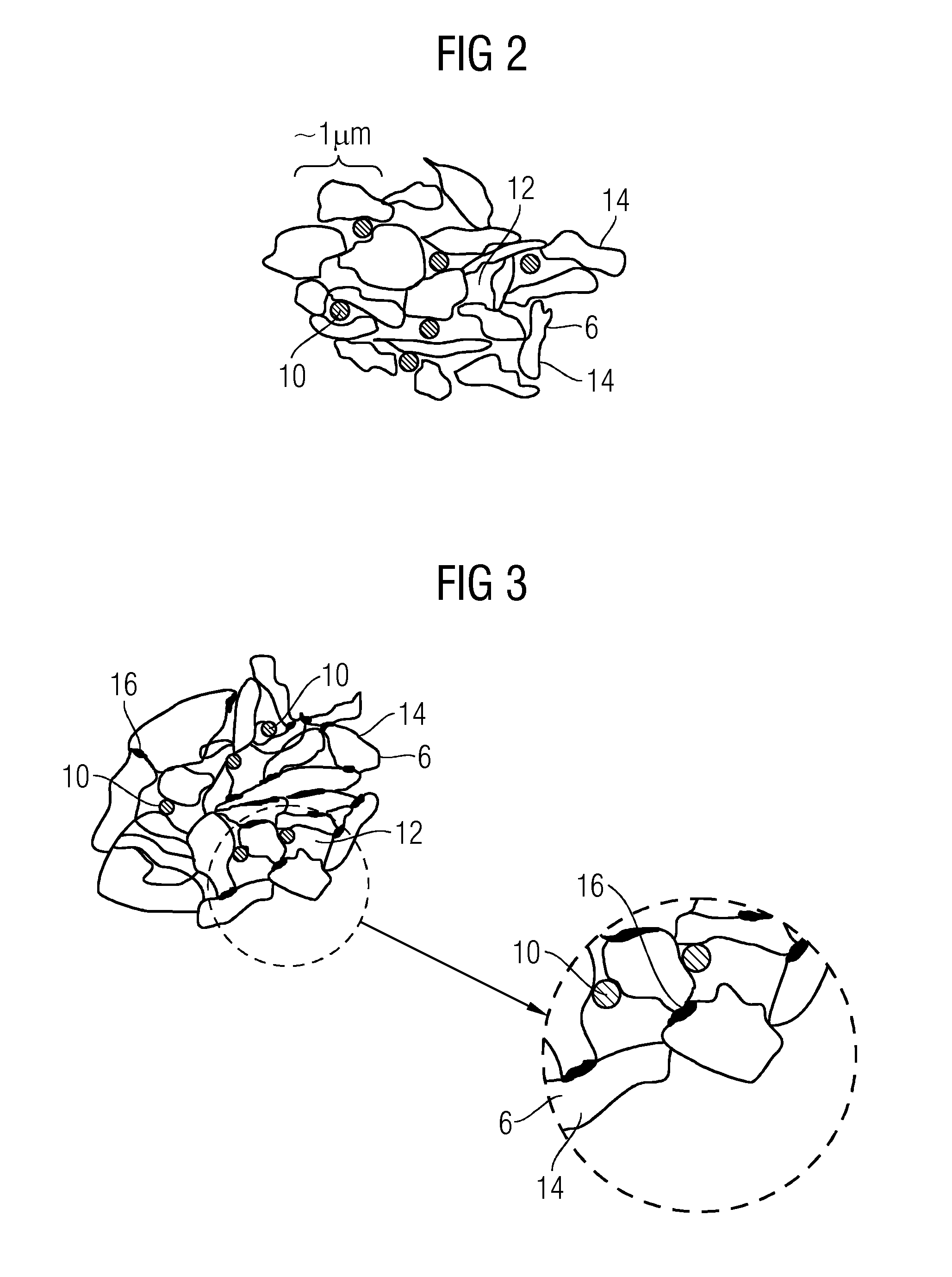
[0024]For this reason, it is appropriate to use a storage structure 2 made from porous material on the negative electrode as energy storage medium, the latter contain...


PUM

PropertyMeasurementUnit
particle size distributionaaaaaaaaaa

Abstract

A storage structure of an electrical energy storage cell is provided having an active storage material, wherein the active storage material has a particle size distribution which has a d5 value of at least 0.1 μm and a d50 value of between 0.8 μm and 1.1 μm, wherein the d95 value of the particle size distribution is lower than 10 μm.

Description

CROSS REFERENCE TO RELATED APPLICATIONS[0001]This application is the US National Stage of International Application No. PCT / EP2013 / 055187 filed Mar. 14, 2013, and claims the benefit thereof. The International Application claims the benefit of German Application No. DE 102012204170.2 filed Mar. 16, 2012. All of the applications are incorporated by reference herein in their entirety.FIELD OF INVENTION[0002]The invention relates to a storage structure of an electrical energy storage cell.BACKGROUND OF INVENTION[0003]Excess electrical power originating, for example, from renewable energy sources can be stored in the power grid only to a limited degree. This also applies to excess power which is obtained in fossil power plants when they are running within the optimal economic load range but the power is not being demanded by the consumer from the grid. There are various large-scale storage devices for intermediate storage of this excess power in relatively large amounts. One of these is,...

Claims


Application Information

Patent Timeline
Patent Type & Authority Applications(United States)
IPC IPC(8): H01M4/36H01M4/38H01M12/02H01M4/52
CPCH01M4/36H01M4/523H01M2004/021H01M12/02H01M4/38H01M4/628H01M12/08H01M2300/0068Y02E60/10
Inventor LANDES, HARALDSCHUH, CARSTENSOLLER, THOMAS
Owner SIEMENS AG
Why Eureka
Try Eureka