Hybrid converter and wind power generating system

a hybrid converter and wind power technology, applied in the direction of electric generator control, machines/engines, mechanical equipment, etc., can solve the problems of not being able to meet the requirements for the voltage rating and power rating of the voltage source converter cannot meet the requirements of long distance transmission of inland wind power, etc., to achieve high system reliability and increase the voltage rating and power rating of the converter.

Active Publication Date: 2015-05-28
HUAZHONG UNIV OF SCI & TECH
View PDF5 Cites 28 Cited by
  • Summary
  • Abstract
  • Description
  • Claims
  • Application Information

AI Technical Summary

Benefits of technology

[0024]The hybrid converter of the present invention features self-commutating capability, is able to directly convert wind power to DC power, and can be independently applied to a wind farm by serially connecting the first line commutated converter, the second line commutated conve...

Problems solved by technology

However, a bottleneck of rapid wind power development is that most wind power bases are located in remote areas where power load of local AC power grids is low, self-consumption thereof is poor, and wind energy is adversely distributed with respect to power demand, which make it necessary to transfer most wind power via large-scale wind power transmission for consumption at a load center.
Since in operation, the LCC requires an external AC voltage source to provide commutating voltage thereto, while a wind farm is a passive AC system, and it is difficult to establish AC voltage using multiple wind power generators that are individually distributed, therefore, the LCC is not suitable to directly convert the wind power to DC.
However, there has been no report of applying the voltage source converter for transmission of inland wind power over long distance.
Applying the voltage source converter for transmission of inland wind power over long distance faces a main challenge that rated voltage and rated power of the voltage source converter cannot meet the requirement for long distance transmiss...

Method used


Image

  • Hybrid converter and wind power generating system
  • Hybrid converter and wind power generating system
  • Hybrid converter and wind power generating system

Examples


Embodiment Construction

[0033]For clear understanding of the objectives, features and advantages of the invention, detailed description of the invention will be given below in conjunction with accompanying drawings and specific embodiments. It should be noted that the embodiments are only meant to explain the invention, and not to limit the scope of the invention.

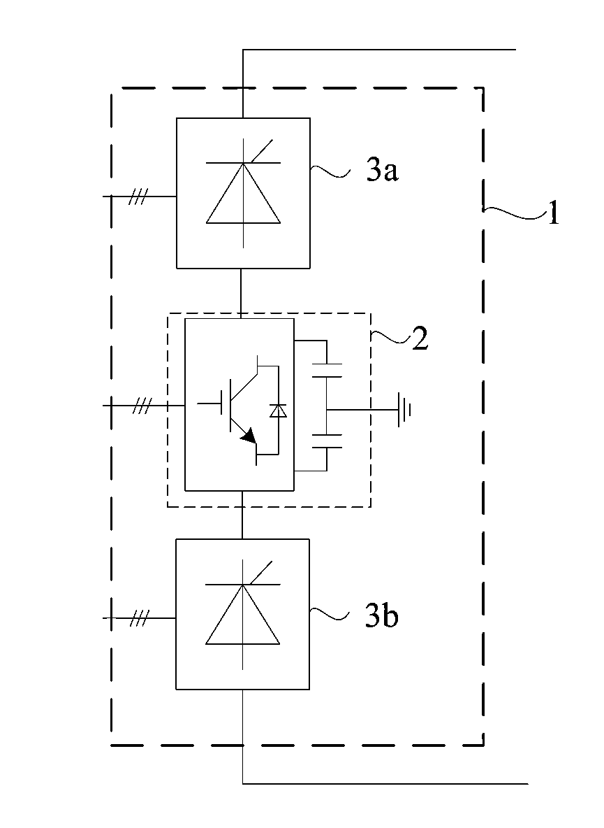
[0034]The hybrid converter of an exemplary embodiment of the invention is mainly applied to the field of a wind power generating system that is accessed to a power system via HVDC, and capable of addressing problems that rated voltage and a rated power thereof are inadequate for large-scale power transmission over long distance as a conventional voltage source converter is used for transmission of inland wind power over long distance, and that a conventional line commutated converter cannot be directly employed for transmission of wind power in the absence of commutating voltage provided by an external AC voltage source.

[0035]As shown in FIG. 1 an...


PUM


Abstract

The present invention discloses a hybrid converter and a wind power generating system, the hybrid converter comprising a voltage source converter, a line commutated converter and a line commutated converter, a positive DC terminal of the voltage source converter is connected to a negative DC terminal of the line commutated converter, a positive DC terminal of the line commutated converter is connected to a positive DC transmission line, a negative DC terminal of the voltage source converter is connected to a positive DC terminal of the line commutated converter, and a negative DC terminal of the line commutated converter is connected to a negative DC transmission line. The present invention features a self-commutating capability, can be directly connected to a wind farm to convert wind power to DC power, and is able to improve rated voltage and rated power of the hybrid converter, technology of each component thereof is mature, and system reliability thereof is high.

Description

FIELD OF THE INVENTION[0001]The present invention relates to the power transmission and distribution filed, and more particularly to a hybrid converter and a wind power generating system.BACKGROUND OF THE INVENTION[0002]Since 2005, the installed wind power capacity has kept increasing rapidly, and annual increase of the installed wind power generating capacity is more than 20% during 2005-2011. Since 2011, development of wind power has entered into a stable period, and annual increased wind power generating capacity is approximately 40 GW. However, a bottleneck of rapid wind power development is that most wind power bases are located in remote areas where power load of local AC power grids is low, self-consumption thereof is poor, and wind energy is adversely distributed with respect to power demand, which make it necessary to transfer most wind power via large-scale wind power transmission for consumption at a load center. High voltage DC transmission (HVDC) is a commonly-used tech...

Claims


Application Information

Patent Timeline
IPC IPC(8): H02M7/145H02M7/21F03D9/00H02J3/36H02M1/00
CPCH02M7/145F03D9/005H02M7/21H02J3/36Y02E10/76H02M7/19H02M7/25H02M7/487Y02E60/60F03D9/257Y02E10/72H02M1/0077H02M7/4835H02M1/0095
Inventor LIN, WEIXINGWEN, JINYUWANG, SHAORONGCHENG, SHIJIE
Owner HUAZHONG UNIV OF SCI & TECH
Why Eureka
Try Eureka