Ultrasound tranducer assembly and method for driving an ultrasound transducer head

a transducer head and ultrasonic technology, applied in the direction of ultrasonic/sonic/infrasonic image/data processing, mechanical vibration separation, application, etc., can solve the problem of limited power consumption of the possible combination of different ultrasound transducer excitation within the transducer head, and achieve the effect of large power spectrum

Inactive Publication Date: 2015-05-28
KONINKLJIJKE PHILIPS NV
View PDF5 Cites 3 Cited by
  • Summary
  • Abstract
  • Description
  • Claims
  • Application Information

AI Technical Summary

Benefits of technology

[0004]It is an object of the present invention to provide an improved ultrasound transducer assembly comprising an ultrasound transducer head and a corresponding driving method for driving an ultrasound transducer head having a large power spectrum to drive different ultrasound transducer excitation with different power consumption.

Problems solved by technology

Due to the technical limitations of the power supply and the connection cable, the power spectrum provided to the transducer head is low and, therefore, the possible combination of different ultrasound transducer excitation within the transducer head is limited to the respective power consumption.

Method used


Image

  • Ultrasound tranducer assembly and method for driving an ultrasound transducer head
  • Ultrasound tranducer assembly and method for driving an ultrasound transducer head
  • Ultrasound tranducer assembly and method for driving an ultrasound transducer head

Examples


Embodiment Construction

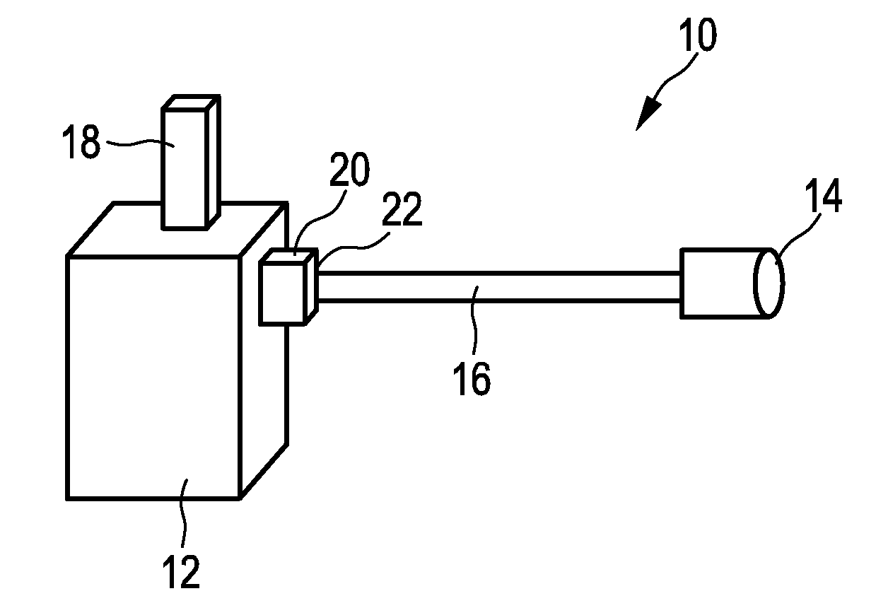
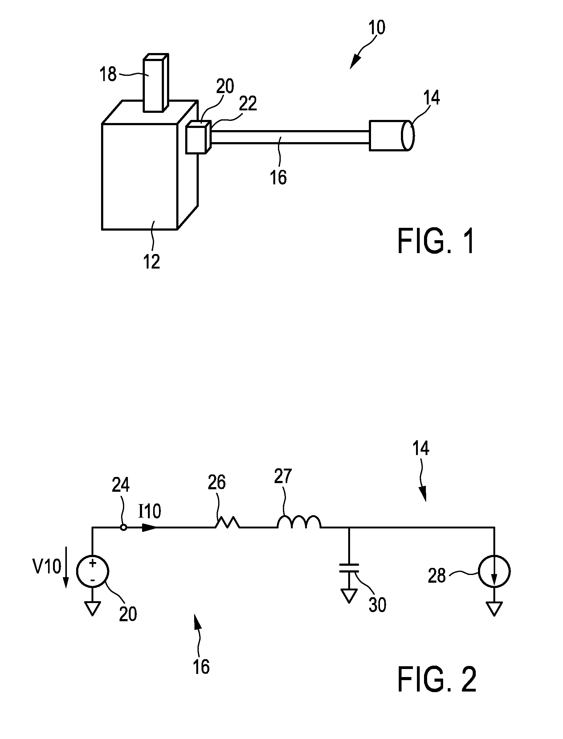
[0046]FIG. 1 shows a schematic diagram of an ultrasound system generally denoted by 10. The ultrasound system 10 comprises a base station 12 and an ultrasound transducer head 14 which are electrically connected to each other by a transducer cable 16. The base station 12 comprises a display 18. The base station comprises a power supply 20 for providing electrical power to the ultrasound transducer head 14 and a connector 22 for connecting the transducer cable 16 to the power supply 20.

[0047]The transducer head 14 comprises one or more ultrasound transducers, e.g. an ultrasound imaging transducer, an elastography ultrasound transducer, a combined transducer for shear wave elastography imaging and / or other therapy transducer elements. The power supply 20 provides electrical power via the transducer cable 16 to the ultrasound transducer in the ultrasound transducer head 14. The transducer cable 16 is a flexible cable. The base station 12 comprises the display 18 to display images e.g. p...


PUM


Abstract

The present invention relates to an ultrasound transducer assembly (10) comprising: an ultrasound transducer head (14), an electrical conductor (16) for connecting the transducer head (14) to an electrical power supply (20) of a base station (12) and for transmitting electrical power from the power supply (20) to the transducer head (14), a connector element (22) for connecting the electrical conductor (16) to the power supply (20) and for receiving an input voltage (V20) from the power supply (20), and a capacitor (34) electrically connected or electrically connectable to the electrical conductor (16) for storing electrical charge, wherein the capacitor (34) has a capacitance larger than or equal to 100 μF.

Description

FIELD OF THE INVENTION[0001]The present invention relates to an ultrasound transducer assembly and to a method for driving an ultrasound transducer head.BACKGROUND OF THE INVENTION[0002]In the field of ultrasound imaging of shear waves it is known to use ultrasound excitations of two different energy levels as described in U.S. Pat. No. 7,252,004. A first high energy excitation called a “push pulse” is used to excite movement in the tissue. A series of subsequent low energy excitations is used to form an image of the resulting tissue motion. Image guided ultrasound therapy also requires excitations of two different energy levels, one for therapy and the other for imaging. It is desirable to perform shear wave imaging or therapy employing transducers for three dimensional imaging as described in U.S. Pat. No. 6,013,032. These transducers for 3D imaging have transmit excitation circuitry imbedded within the transducer assembly. Ultrasound imaging systems are known to have a base stati...

Claims


Application Information

Patent Timeline
Patent Type & Authority Applications(United States)
IPC IPC(8): A61B8/00A61B8/08
CPCA61B8/56A61B8/485A61B8/4444B06B1/0215B06B2201/76B06B1/02
Inventor SAVORD, BERNARD JOSEPHNNADI, CHILEZIE UMAROBINSON, ANDREW LEE
Owner KONINKLJIJKE PHILIPS NV
Why Eureka
Try Eureka