Turbocharger with variable turbine geometry having grooved guide vanes
- Summary
- Abstract
- Description
- Claims
- Application Information
AI Technical Summary
Benefits of technology
Problems solved by technology
Method used
Image

Examples
Embodiment Construction
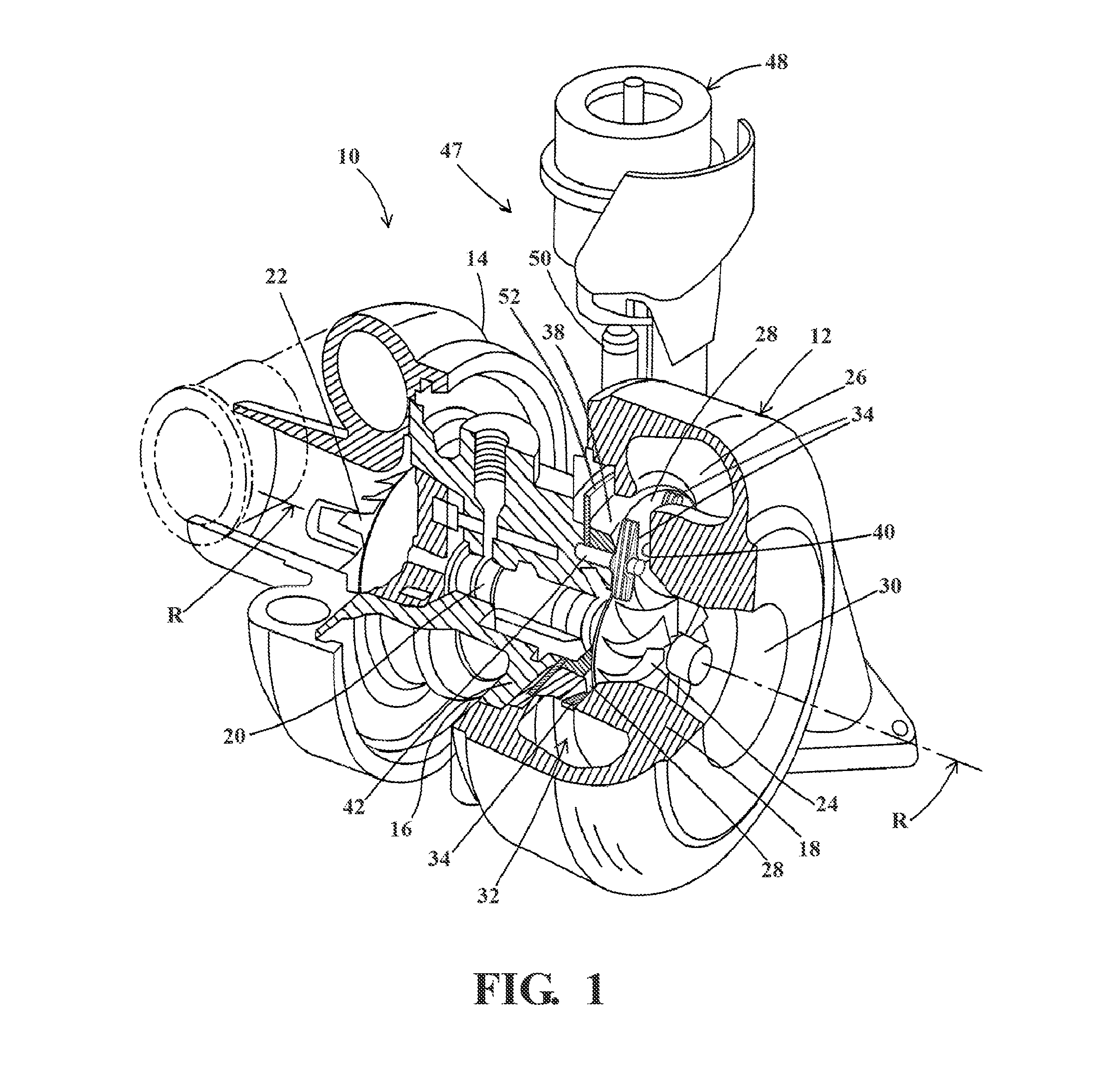
[0019]Referring to the Figures, a turbocharger is illustrated generally at 10 in FIG. 1. The turbocharger 10 includes a housing assembly 12 comprising a compressor housing 14, a bearing or center housing 16, and a turbine housing 18 that are connected to each other. The bearing housing 16 supports a rotatable shaft 20 that extends in an axial direction and defines an axis of rotation R. A compressor impellor 22 is mounted on one end of the shaft 20 and is housed within the compressor housing 14. A turbine wheel 24 is mounted on an opposite end of the shaft 20 and is housed within the turbine housing 18. The turbine housing 18 defines a volute 26 that is coupled to an exhaust manifold (not shown) and evolves into a wheel inlet 28 for directing a flow of exhaust gas from the exhaust manifold to the turbine wheel 24. As is well known in the art, the turbine wheel 24 is rotatably driven by the exhaust gas supplied from the exhaust manifold, which rotates the shaft 20, thereby causing th...
PUM
 Abstract
Description
Claims
Application Information
 - R&D
- Intellectual Property
- Life Sciences
- Materials
- Tech Scout
- Unparalleled Data Quality
- Higher Quality Content
- 60% Fewer Hallucinations
Browse by: Latest US Patents, China's latest patents, Technical Efficacy Thesaurus, Application Domain, Technology Topic, Popular Technical Reports.
© 2025 PatSnap. All rights reserved.Legal|Privacy policy|Modern Slavery Act Transparency Statement|Sitemap|About US| Contact US: help@patsnap.com