Spectacle lens and method for making the same

a manufacturing method and technology for spectacle lenses, applied in the direction of spectacles/goggles, paper/cardboard containers, instruments, etc., to achieve the effect of cost-effective and accelerate the manufacturing process of spectacle lenses for individual wearers

Active Publication Date: 2015-06-04
CARL ZEISS VISION INT GMBH +1
View PDF7 Cites 47 Cited by
  • Summary
  • Abstract
  • Description
  • Claims
  • Application Information

AI Technical Summary

Benefits of technology

[0017]Therefore, it is an object of the current invention to provide a method for manufacturing a spectacle lens and a spectacle lens

Problems solved by technology

However, even with current resolutions, such printing methods are time-consuming and lead to lenses wherein the step-like arrang

Method used


Image

  • Spectacle lens and method for making the same
  • Spectacle lens and method for making the same
  • Spectacle lens and method for making the same

Examples


Embodiment Construction

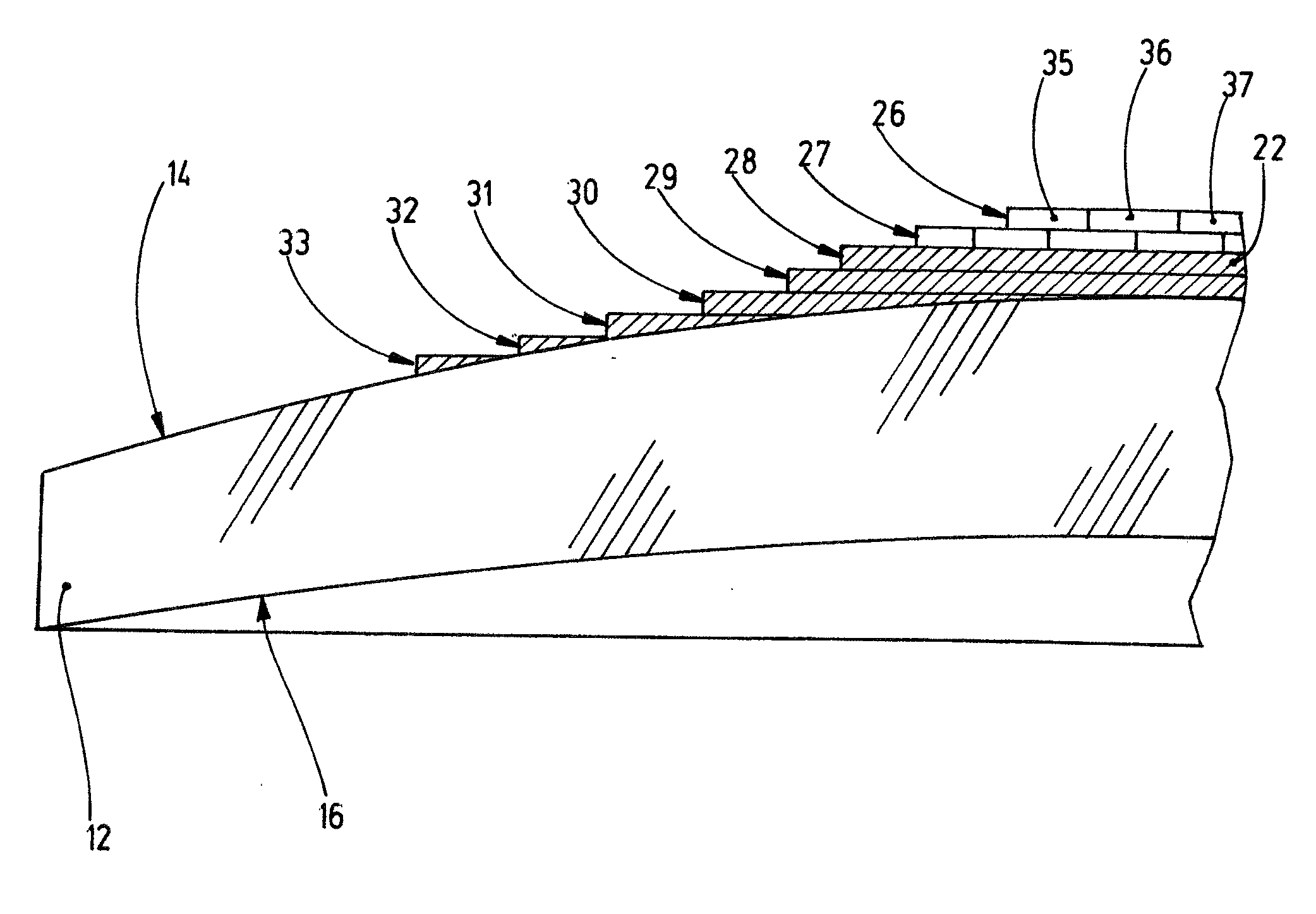
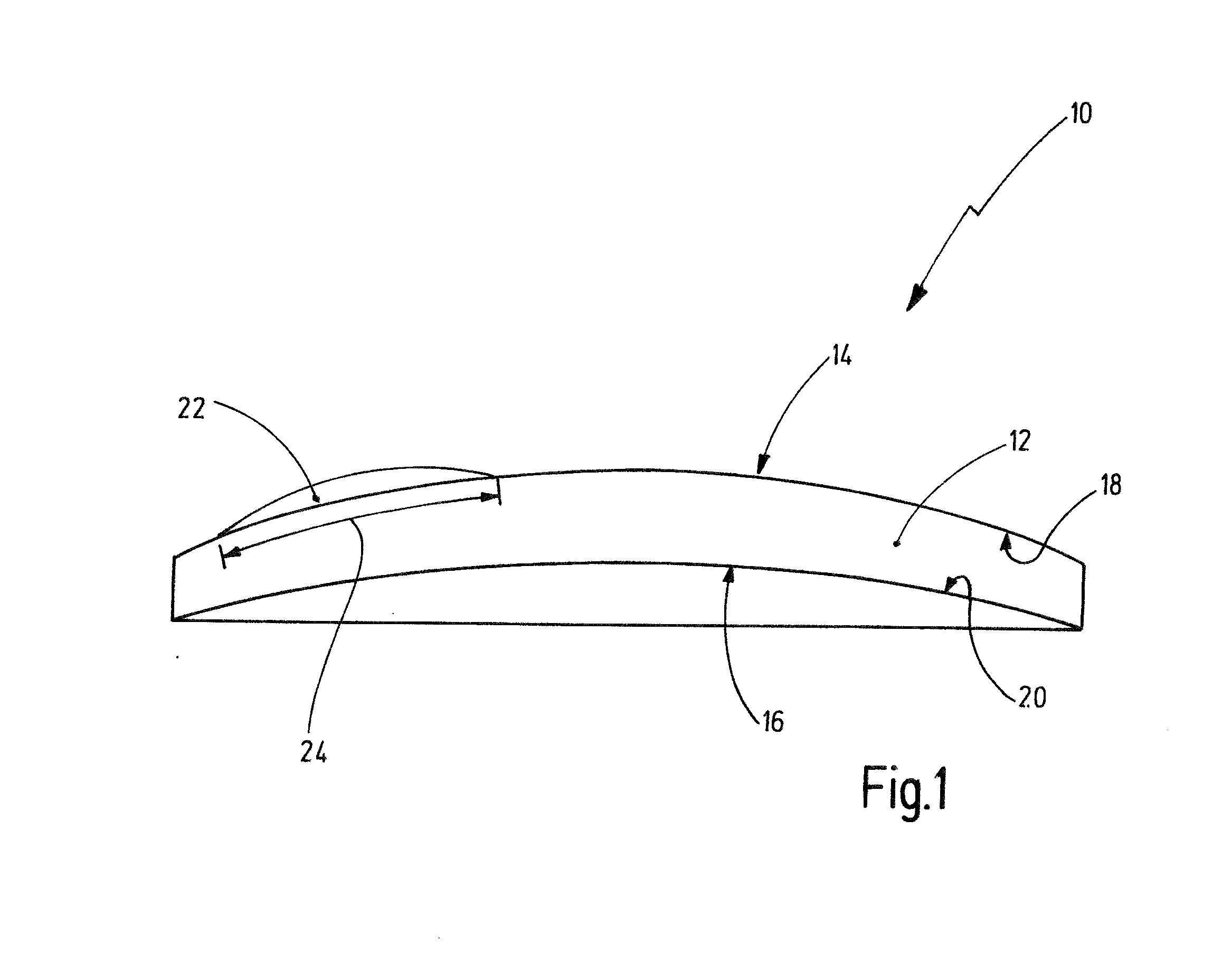
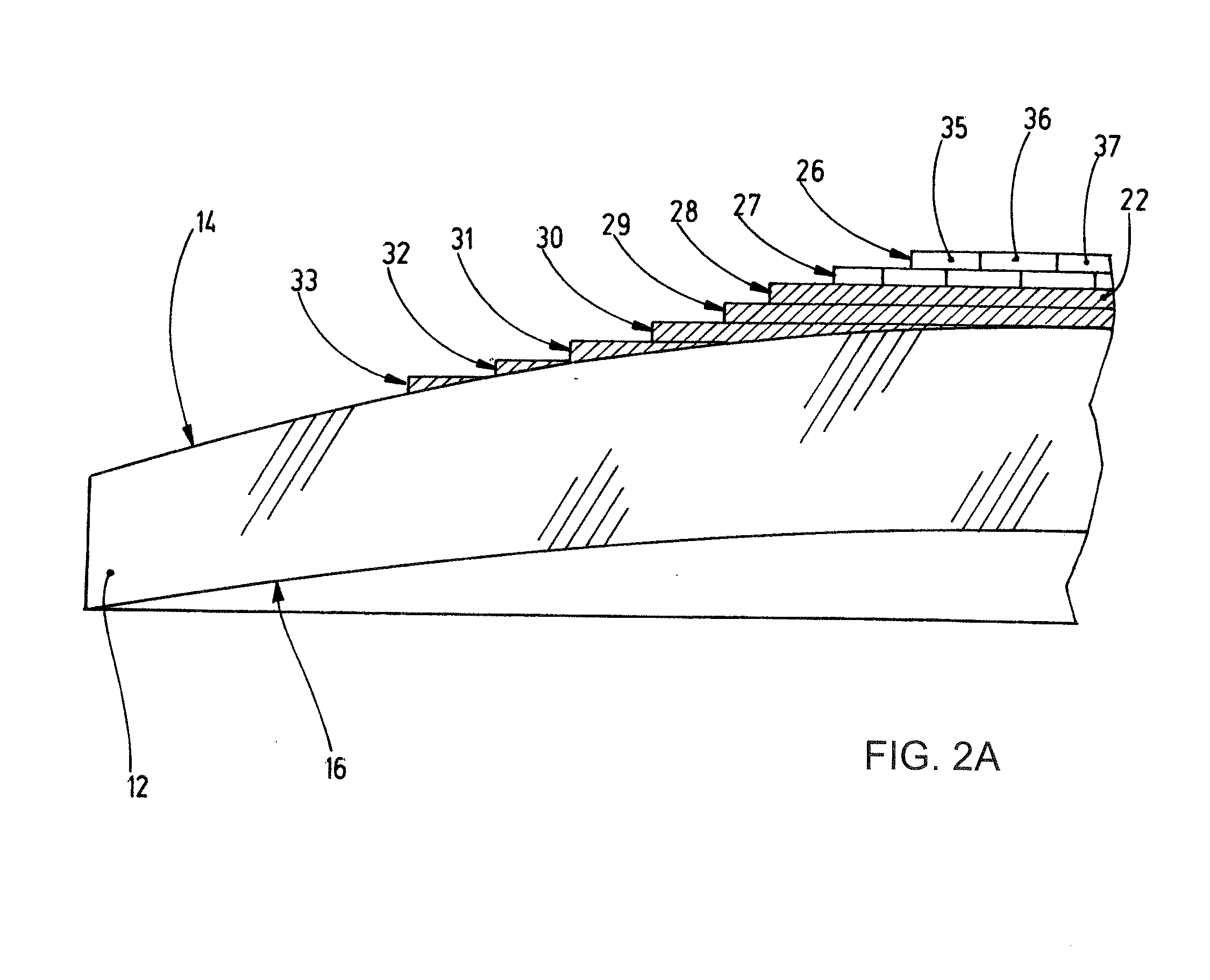
[0140]FIG. 1 shows a spectacle lens 10 in a first embodiment. The spectacle lens 10 comprises an integral main lens 12. The integral main lens 12 may have been casted with subsequent grinding and polishing. Alternatively, the integral main lens 12 may also be grinded and polished out of a raw blank or provided via injection molding. In particular, the integral main lens is made of plastic, in particular CR39 or MR7. In particular, the integral main lens 12 is a spherical power lens or astigmatic power lens. That means the integral main lens 12 has a spherical power in at least one meridian focusing a collimated light beam into a single focus. The integral main lens 12 has a front surface 14 having a main curvature 18 and a back surface 16 having a main curvature 20.

[0141]In the example of FIG. 1, the integral main lens 12 is rotationally symmetric and, hence, has an optical axis through which meridian planes run. Hence, the cross section as shown in FIG. 1 is such a meridian plane. ...


PUM

PropertyMeasurementUnit
Fractionaaaaaaaaaa
Poweraaaaaaaaaa
Refractive indexaaaaaaaaaa

Abstract

A method for manufacturing a spectacle lens includes the steps of providing an integral main lens. The integral main lens has a front surface and a back surface and is at least one selected from a group consisting of a spherical power lens, an astigmatic power lens, and a lens having a main curvature of the front surface in a first meridian and a main curvature of the back surface in the first meridian which are different so as to provide for a spherical power different from zero; and applying at least one additional lens element to at least a part of the front surface and/or at least a part of the back surface, wherein the at least one additional lens element includes at least one layer having a multitude of layer elements, in particular printed layer elements. Further, the invention is directed to a corresponding spectacle lens.

Description

CROSS-REFERENCE TO RELATED APPLICATIONS[0001]This application claims the priority of European patent application EP13195130.3, filed Nov. 29, 2013, the entire content of which is incorporated herein by reference.BACKGROUND OF THE INVENTION[0002]The current invention is related to a method for manufacturing a spectacle lens and a spectacle lens.[0003]It is well known in the art that spectacle lenses can be used for the correction of visual impairment. Ideally, a spectacle lens is not only manufactured to fit the individual needs of a spectacle wearer best possible but also at minimum cost. Spectacle lenses are described by the shapes of their back surface and their front surface. Typically, the visual impairment of a spectacle wearer is described by the so-called prescription that provides parameters for spherical power, astigmatic power and prismatic power to correct for the aberrations of the wearer's eye.[0004]Different processes for manufacturing such spectacle lenses are known. ...

Claims


Application Information

Patent Timeline
IPC IPC(8): G02C7/06B29D11/00G02B1/04
CPCG02C7/068G02C7/06B33Y80/00B29D11/00028B33Y10/00G02B1/041G02C7/021G02C2202/12G02C2202/16G02C7/022B29D11/00432Y10T156/10Y10T156/1089
Inventor MESCHENMOSER, RALFKRATZER, TIMOBEGLEY, PARAICBROWN, STEPHEN
Owner CARL ZEISS VISION INT GMBH
Why Eureka
Try Eureka