Method of controlling a power factor correction converter and related closed-loop control system

Active Publication Date: 2015-06-04
STMICROELECTRONICS INT NV
View PDF4 Cites 11 Cited by
  • Summary
  • Abstract
  • Description
  • Claims
  • Application Information

AI Technical Summary

Benefits of technology

[0017]Deep studies carried out by the inventors have led to conclude that state-of-art techniques aiming at improving efficiency at light load conditions are not capable of dramatically reducing switching losses while keeping good total harmonic distortion (THD) and power factor (PF) and ultimately meeting most recent norms and standards. Besides, burst mode techniques seem unsuit

Problems solved by technology

Deep studies carried out by the inventors have led to conclude that state-of-art techniques aiming at improving efficiency at light load conditions are not capable of dramatically reducing switching losses while keeping good total harmonic distortion (THD) and power factor (PF) and ultimately meeting most recent norms and standards.
Besides, burst mode techniques seem unsuitabl

Method used


Image

  • Method of controlling a power factor correction converter and related closed-loop control system
  • Method of controlling a power factor correction converter and related closed-loop control system
  • Method of controlling a power factor correction converter and related closed-loop control system

Examples


Example

[0038]The following description has the purpose of illustrating the general principles of the disclosure and should not be taken in a limiting sense. The scope of the invention is best determined by reference to the appended claims.

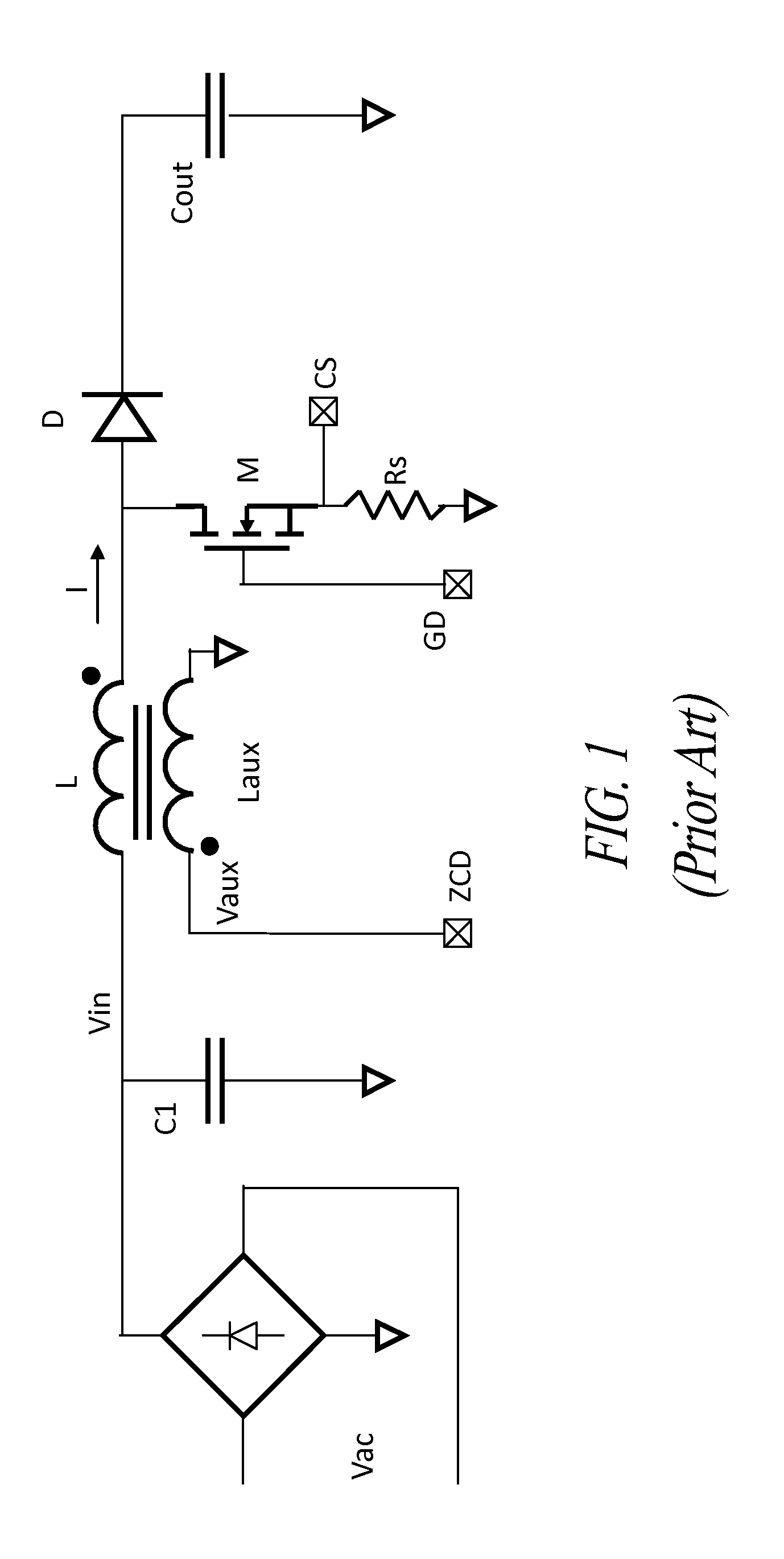
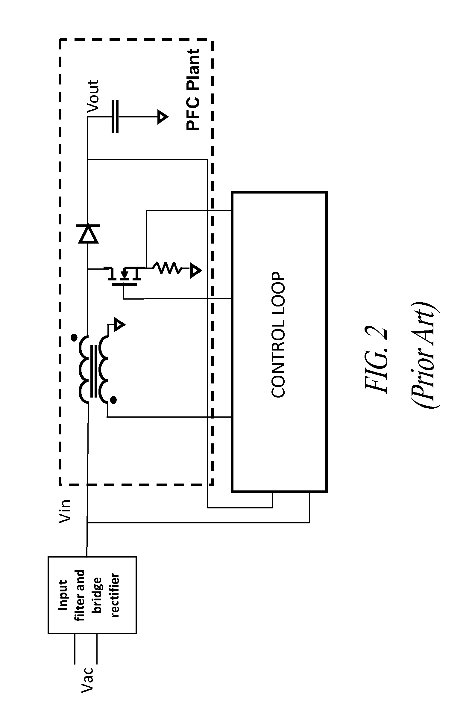
[0039]The peculiar aspects of this disclosure are hereafter described for the case of one of common PFC circuit configurations though the characteristic features of the disclosure that will be described may be embodied in any other PFC circuit configuration commonly being used by adapting, in the described exemplified manner, the control circuit of the power factor correction converter (PFC).

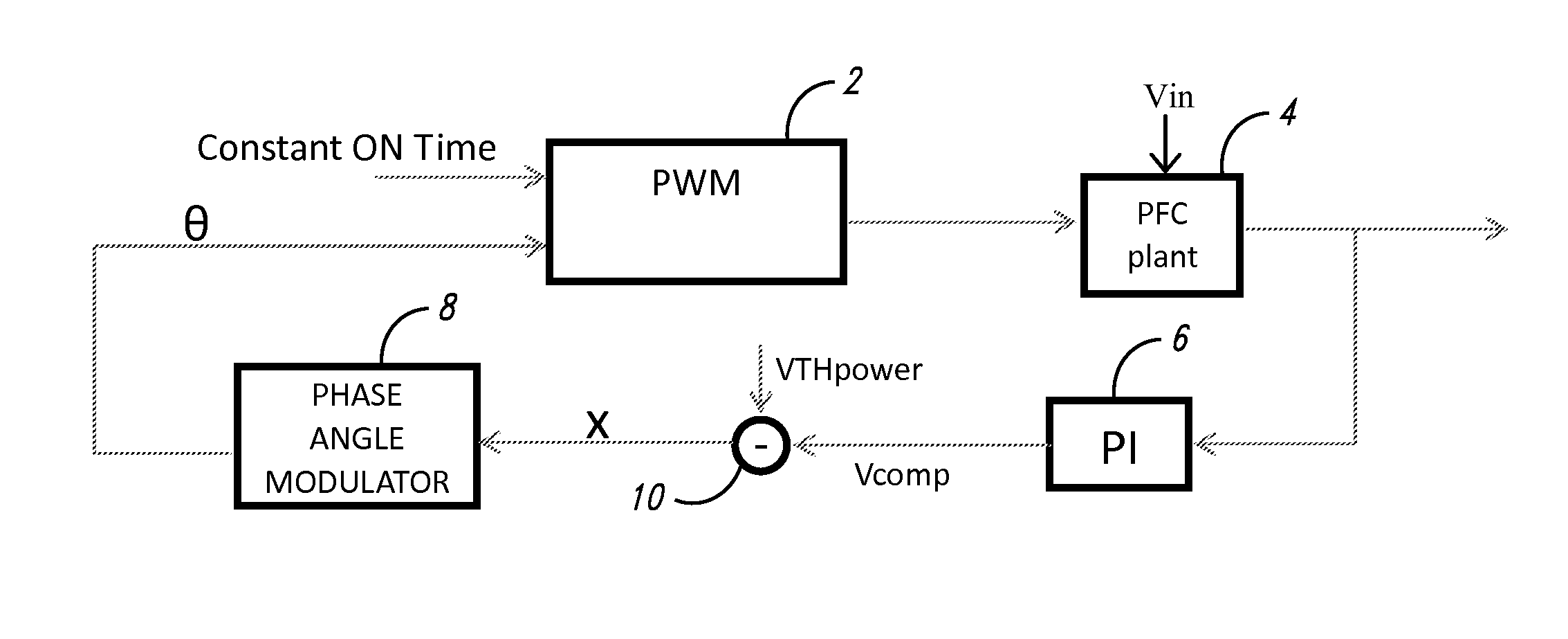
[0040]According to this disclosure, a control block determines phase intervals of the input voltage during which switching cycles are to be skipped. A schematic time graph that illustrates the herein disclosed technique is shown in FIG. 4. Switching cycles are skipped in a phase domain (“skipping area”) including zero-crosses of the rectified input voltage Vin (or, eq...


PUM


Abstract

A method controls a power factor correction converter that includes a boost inductor and a switch. The method generates a sense signal representing a rectified AC input voltage or an inductor current through the boost inductor, turns on the switch in response to determining, based on the sense signal, a zero current condition through the boost inductor, turns off the switch after an on-time interval, generates a feedback signal based on an output voltage of the converter, and compares the feedback signal with a threshold. If the feedback signal is smaller than the threshold, the method generates a command signal, representing a phase domain including 0 and π, based on the feedback signal and the power threshold, and keeps the switch off when a phase of the input rectified AC voltage or of the inductor current is in the phase domain even if the zero current condition has been determined.

Description

BACKGROUND[0001]1. Technical Field[0002]This disclosure relates to electronic control circuits, and more particularly to a method of controlling a power factor correction converter and a related closed-loop control system of a power factor correction converter.[0003]2. Description of the Related Art[0004]Basically, a common example as depicted in FIG. 1, a transition mode (TM) power factor correction converter (PFC) may comprise a boost inductor L, a switch M, a diode D, an output tank capacitor Cout. In the contemplated example, an auxiliary winding Laux is magnetically coupled with the inductor as one exemplary way for sensing a condition of zero current (or zero crossing) in the boost inductor.[0005]However, other ways, equally familiar to the skilled reader, may be chosen, for example a sense resistor in a recirculation current path of the boost inductor through the ground node may be used in lieu of an auxiliary winding.[0006]Control circuit means, commonly based on a microcont...

Claims


Application Information

Patent Timeline
IPC IPC(8): H02M1/42H02M1/00
CPCH02M1/4208H02M1/4225Y02B70/10H02M1/0032
Inventor CASTELLI, CLAUDIAADRAGNA, CLAUDIO
Owner STMICROELECTRONICS INT NV
Why Eureka
Try Eureka