projector

a projector and heat sink technology, applied in projectors, color television details, instruments, etc., can solve the problems of inefficient cooling of cooling liquid to a desired temperature, inefficient further upsizing of the heat sink as a means, and inefficient cooling of the cooling liquid. , to achieve the effect of efficient cooling and efficient cooling of the optical devi

Active Publication Date: 2015-06-04
SEIKO EPSON CORP
View PDF2 Cites 11 Cited by
  • Summary
  • Abstract
  • Description
  • Claims
  • Application Information

AI Technical Summary

Benefits of technology

[0028]Thereby, the heat generated in the optical device due to the light from the light source may be transferred to the heat receiving part via the cooling liquid. Further, as described above, the cooling device efficiently transfers the heat of the heat receiving part to the heat sink using the thermoelectric conversion element and the heat pipe, and accordingly, the cooling liquid may be efficiently cooled. Thus, cooling of the optical device holding unit in which the cooling liquid cooled in the heat receiving part circulates, and efficient cooling of the optical device may be performed.

Problems solved by technology

However, in the thermoelectric conversion unit disclosed in Patent Document 1, it may be considered that the heat received by the heat receiving jacket is not efficiently transferred to both sides of the heat sink, and it may be difficult that the cooling liquid is cooled to a desired temperature.
Or, further upsizing of the heat sink is inefficient as means for transferring heat to the whole heat sink.
Upsizing of the cooling device is problematic, and increase in wind speed of the cooling fan leads to a problem of increase in noise.
Therefore, the expensive heat receiving part having the complex structure may be formed as a common member that can be mounted on various projectors.

Method used


Image

  • projector
  • projector
  • projector

Examples


first embodiment

[0040]As below, a projector according to the first embodiment will be explained with reference to the drawings.

[0041]The projector of the embodiment modulates light output from a light source in response to image information and enlarges and projects the modulated light on a projection surface such as a screen.

Main Configuration of Projector

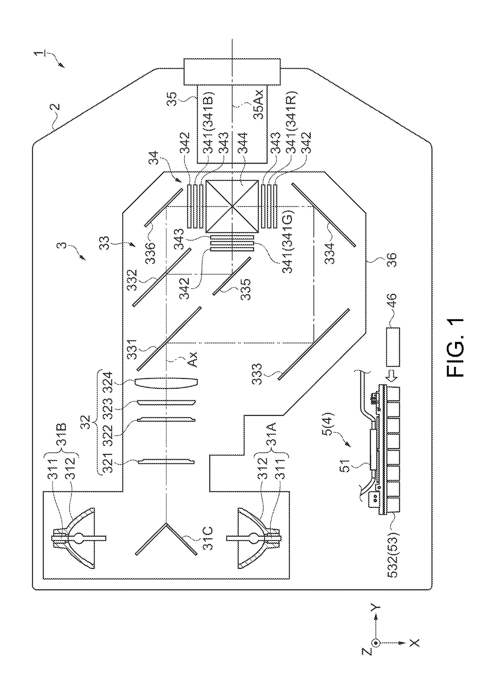
[0042]FIG. 1 is a schematic diagram showing a main configuration of a projector 1 of the first embodiment.

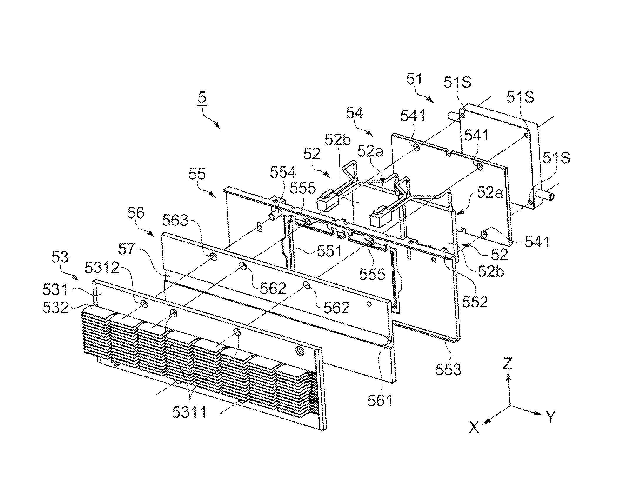
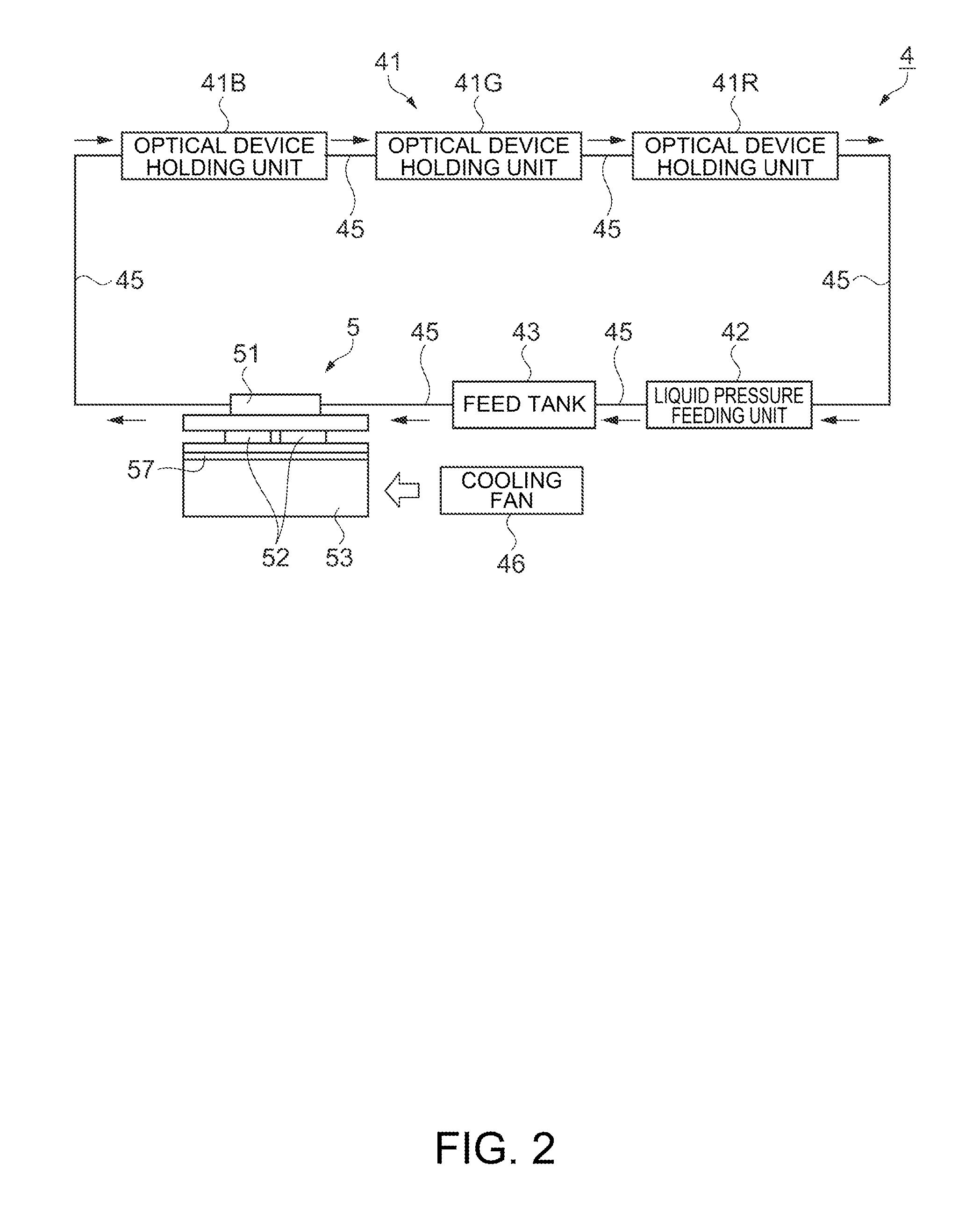
[0043]As shown in FIG. 1, the projector 1 includes an exterior housing 2 forming an exterior, a control unit (not shown), an optical unit 3 having light sources 311, and a cooling device 4. Though not illustrated, a power supply device that supplies power to the light sources 311 and the control unit etc. are provided inside of the exterior housing 2. Note that, in FIG. 1, only a part of the cooling device 4 is shown. Further, as below, for convenience of explanation, an output direction of light modulated in the projector 1 is referred to as...

second embodiment

[0125]As below, a projector according to the second embodiment will be explained with reference to the drawings. In the following explanation, the same configurations and the same members as those of the projector 1 of the first embodiment have the same signs and their detailed explanation will be omitted or simplified.

[0126]The projector of the embodiment (not shown) includes a heat exchange unit 7 having a different configuration from that of the heat exchange unit 5 in the projector 1 of the first embodiment.

[0127]FIG. 7 is a perspective view of the heat exchange unit 7 of the embodiment. FIGS. 8A and 8B are exploded views of the heat exchange unit 7, and FIG. 8A is a view seen from one side and FIG. 8B is a view seen from the other side. FIG. 9 is a sectional view of the heat exchange unit 7.

[0128]As shown in FIGS. 7, 8A, and 8B, the heat exchange unit 7 of the embodiment includes a heat sink 71, a fixing frame 72, and a heat pipe 73 having different shapes from those of the hea...

modified example 1

[0141]The heat exchange units 5, 7 of the embodiments include single heat pipes 57, 73 having shapes nearly along straight lines, however, the number and shape of the heat pipes are not limited to those.

[0142]FIGS. 10A to 10D are schematic diagrams of heat exchange units 8A, 8B, 8C, 8D showing a modified example of the heat exchange unit 7 including the single Peltier device 52, and plan views showing the Peltier devices 52, heat pipes, and heat sinks 82.

[0143]As the heat exchange unit 8A shown in FIG. 10A, two heat pipes 81A each having length nearly a half of the length of the heat pipe 73 of the second embodiment may be provided, and the two heat pipes 81A may be placed along one straight line.

[0144]As the heat exchange unit 8B shown in FIG. 10B, a plurality of heat pipes 81B extending along a straight line like the heat pipe 73 of the second embodiment are provided, and the plurality of heat pipes 81B may be arranged in parallel in a direction orthogonal to the extension directi...


PUM


Abstract

A projector includes a cooling device cooling a liquid crystal panel. The cooling device includes a heat receiving part receiving heat of the liquid crystal panel, a Peltier device having a heat absorbing part that absorbs the heat of the heat receiving part and a heat generating part that generates heat when the absorbing part absorbs heat, a heat sink provided so that heat may be transferred to the heat generating part, and a heat pipe containing a hydraulic fluid inside, in which heat is transferred by convection of the hydraulic fluid. The heat sink has a stacking part superimposed on the Peltier device and a projecting part projecting from the Peltier device as seen from the Peltier device side, and the heat pipe has an interior part located between the Peltier device and the stacking part and an extending part extending along the projecting part.

Description

BACKGROUND[0001]1. Technical Field[0002]The present invention relates to a projector.[0003]2. Related Art[0004]In related art, a projector including a light source, a light modulator that modulates light output from a light source in response to image information and a projection system that projects the light modulated by the light modulator, and projecting an image on a projection surface such as a screen is known. Recently, higher illuminance of the light source has been desired and optical devices of the light modulator etc. have generated heat at higher temperatures, and thus, a projector for efficiently cooling the optical devices has been proposed (for example, see Patent Document 1 (JP-A-2010-250042)).[0005]A projector disclosed in Patent Document 1 includes a liquid cooling device and a cooling fan. The liquid cooling device includes an optical device holding unit, a liquid pressure feeding unit, a heat receiving jacket, a feed tank, a plurality of liquid circulating member...

Claims


Application Information

Patent Timeline
Patent Type & Authority Applications(United States)
IPC IPC(8): H04N9/31
CPCH04N9/3144G03B21/16
Inventor NAGATSU, TAKUROYANAGISAWA, YOSHIYUKITAKAGI, CHIGUSA
Owner SEIKO EPSON CORP
Why Eureka
Try Eureka