
Shaft arrangement and method for relaying torques acting around a rotational axis

Active Publication Date: 2015-06-11
FRAUNHOFER GESELLSCHAFT ZUR FOERDERUNG DER ANGEWANDTEN FORSCHUNG EV
View PDF6 Cites 8 Cited by
  • Summary
  • Abstract
  • Description
  • Claims
  • Application Information

AI Technical Summary

Benefits of technology

The invention provides a shaft arrangement with a smoothly adjustable torsional stiffness that can dampen disruptive rotational oscillations, such as those caused by structurally specific, resonant natural frequencies or drive-side excitation frequencies. The shaft arrangement has a variably adjustable torsional stiffness around its rotational axis, which can be achieved with simple and cost-effective means. It can be integrated along a shaft that transfers rotational movements and torques, effectively dampening the frequency-specific rotational oscillations that arise from drive-side excitation frequencies.

Problems solved by technology

Rotating systems for transferring rotational movements and torques, for example in the form of mechanical shafts, are subject to operationally induced torsional loads, which can lead to the formation of disruptive rotational oscillations, in particular given a discontinuous introduction of torque along the shaft.
In particular shafts with a long and slender design, which only have a low torsional stiffness for systemic and structural reasons, tend to form such rotational or torsional oscillations, which additionally have resonant natural oscillations at already low frequencies, and hence can permanently detract from the operational comfort and operational acoustics.
In all instances, these oscillations at the very least detract from the operational stability and associated system loadability of the respective shaft.
Typical examples of rotation transferring systems that are sensitive to rotational oscillations include drive trains in motor vehicles, especially since power output in internal combustion engines does not take place continuously through the individual cylinders, as a result of which the power output of the engine as a whole is accompanied by torque fluctuations, which have an especially detrimental impact in particular in cases where the frequency of these fluctuations lies within or is proximate to the natural frequencies for the ensuing rotationally movable systems in the drive train, for example the power train, transmission, steering system, etc.
In these instances, the discontinuities caused by the internal combustion engine can lead to elevated oscillation loads, wear and noise generation, which noticeably detract from driving comfort.
In order to counteract such rotational oscillations, it obviously makes sense to elevate the torsion resistance of rotationally movable components with structural measures, most often by using stable shafts with as massive a design as possible, although this results in an undesired increased weight for the overall system, which would not appear to be beneficial in terms of cost and energy savings.
The disadvantage is that the transected areas yield a torsional stiffness characterizing the component that is irreversible and fixed.
As a consequence, while rotational oscillations can be dampened within a fixed frequency range, work, ageing or system-related, frequency-specific changes take place in the arising natural frequencies of the rotational oscillations, causing the known torque transferring device to reach its technical limits.

Method used


Image

  • Shaft arrangement and method for relaying torques acting around a rotational axis
  • Shaft arrangement and method for relaying torques acting around a rotational axis
  • Shaft arrangement and method for relaying torques acting around a rotational axis

Examples


Embodiment Construction

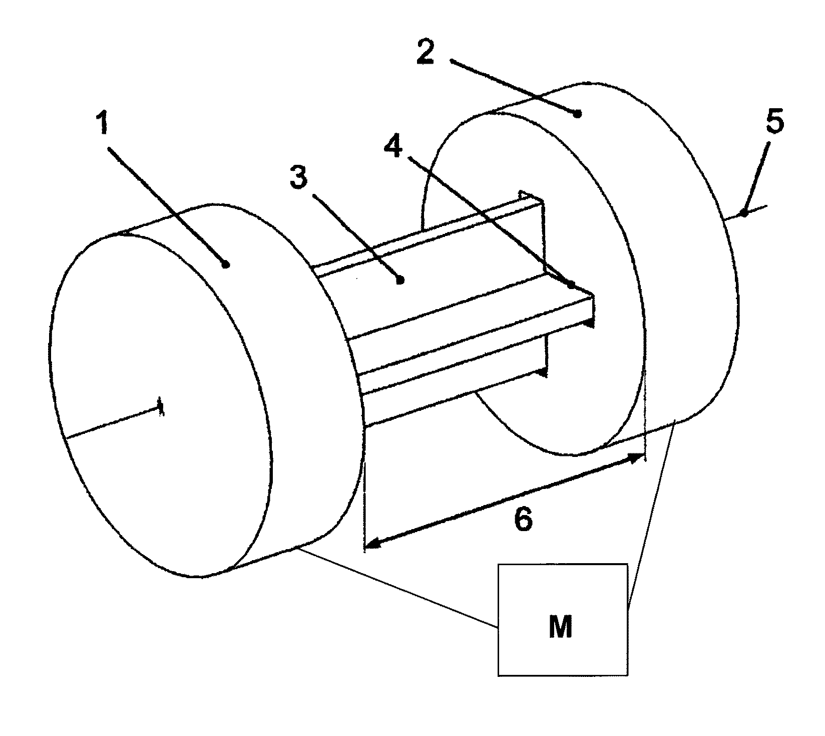
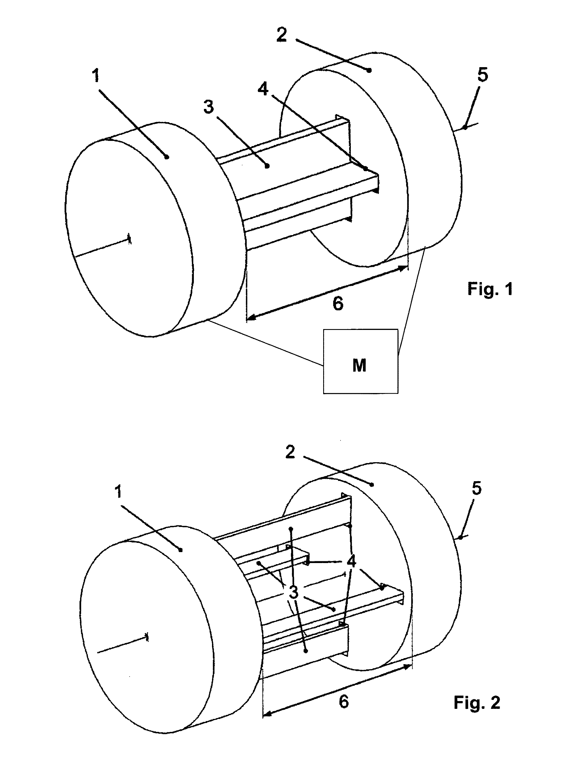
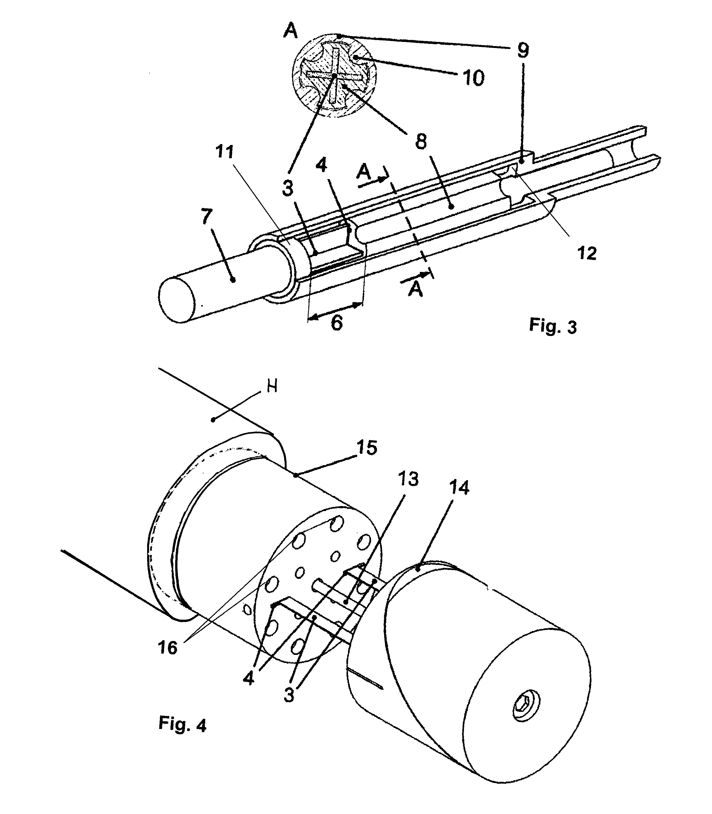
[0034]FIG. 1 depicts a shaft arrangement that is pivoted around a rotational axis 5, whose torsional stiffness acting around the rotational axis 5 can be smoothly adjusted within certain limits. The shaft arrangement includes a first shaft section 1 along with a second shaft section 2, which operatively interact with each other by way of a torsion element 3. The two shaft sections 1 and 2 are mounted so that they can move relative to each other along the rotational axis 5. The torsion element 3, which is a rod or a cord profile having a cross-shaped cross section, is to this end unilaterally rigidly joined on the face with the first shaft section 1. That is, the torsion element 3 is firmly secured to the first shaft section 1 in a torque-proof and axially fixed manner. In contrast, the second shaft section 2 has a cross-shaped opening 4, through which the torsion element 3, which also has a cross-shaped cross section, can be passed in a precisely fitting and axially movable manner a...


PUM


Abstract

A shaft arrangement is disclosed for transmitting torques acting around a rotational axis, with a variably adjustable torsional stiffness acting around the rotational axis and a method for varying the torsional stiffness of a shaft arrangement. The invention includes a first shaft section, having at least one torsion element secured thereto which is not damaged by torque and is axially fixed manner, which is mounted to be dimensionally stable transverse to the rotational axis, a second shaft section spaced axially apart from the first shaft section, to which the at least one torsion element is secured which is not rotatable but is axially movable and that a means for operatively interacts or can be made to operatively interact with the second shaft section for axially moving the second shaft section in relation to the first shaft section and in relation to the at least one torsion element.

Description

CROSS REFERENCE TO RELATED APPLICATION[0001]Reference is made to German Patent Application Serial No. DE 10 2011 120 095.2, filed Dec. 2, 2011, which application is incorporated herein by reference in its entirety.BACKGROUND OF THE INVENTION[0002]1. Field of the Invention[0003]The invention relates to a shaft arrangement for relaying torques acting around a rotational axis, with a variably adjustable torsional stiffness acting around the rotational axis. Further, the invention relates to a method for relaying torques acting around a rotational axis with a variably adjustable torsional stiffness acting around a rotational axis.[0004]2. Description of the Prior Art[0005]Rotating systems for transferring rotational movements and torques, for example in the form of mechanical shafts, are subject to operationally induced torsional loads, which can lead to the formation of disruptive rotational oscillations, in particular given a discontinuous introduction of torque along the shaft. In pa...

Claims


Application Information

Patent Timeline
IPC IPC(8): F16D3/06F16D3/12F16F15/18F16F1/14
CPCF16D3/06F16F15/18F16D3/12F16F1/14F16F15/322F16C3/03F16F1/145F16C2326/01F16F15/10
Inventor FLASCHENTRAGER, DAVIDHANSMANN, JANMELZ, TOBIAS
Owner FRAUNHOFER GESELLSCHAFT ZUR FOERDERUNG DER ANGEWANDTEN FORSCHUNG EV
Learn More