
Optical microscopy systems based on photoacoustic imaging

a photoacoustic imaging and optical microscopy technology, applied in the direction of instruments, specific gravity measurement, measurement devices, etc., can solve the problems of inability to achieve biomedical imaging, inability to generate nonlinear signals, and inability to solve signals ultrasonically time-resolved

Active Publication Date: 2015-06-11
NAT TAIWAN UNIV
View PDF3 Cites 11 Cited by
  • Summary
  • Abstract
  • Description
  • Claims
  • Application Information

AI Technical Summary

Benefits of technology

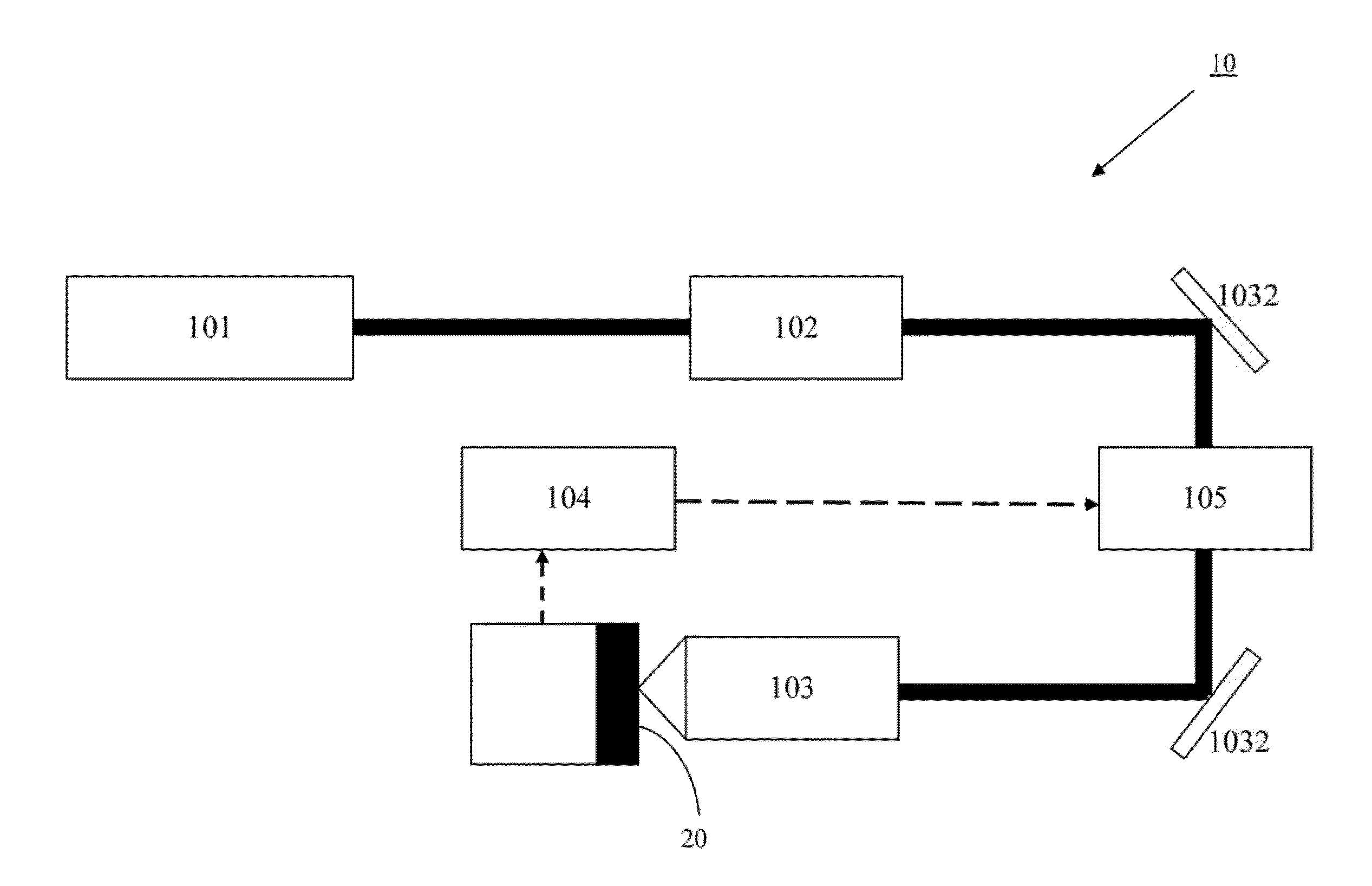
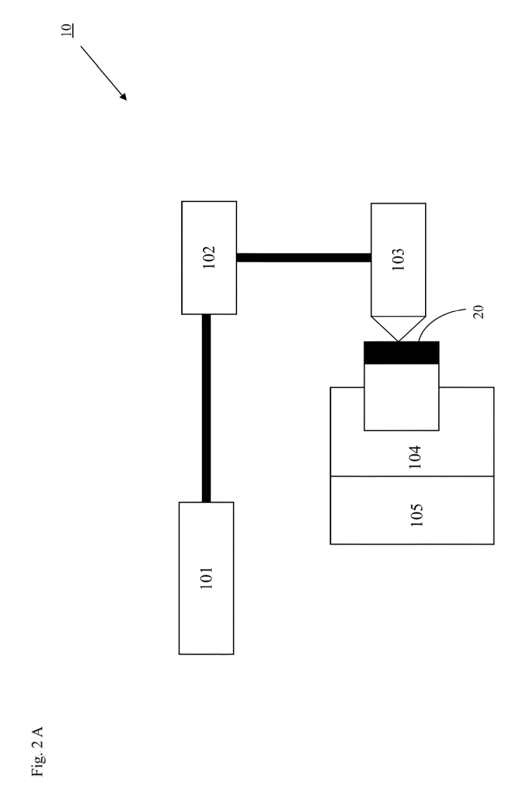
The present invention is a system for optical microscopy that uses laser beams to excite nonlinear processes in a sample. The system detects the resulting photoacoustic waves using an ultrasonic transducer and creates images of the sample through a scanning device. The technical effects include improved resolution and sensitivity in optical microscopy.

Problems solved by technology

These signals can only be ultrasonically time-resolved.
Since strong single-photon absorption usually dominates the overall energy transformation process, the generated nonlinear signals are often buried in noises.
However, several issues make this method infeasible for biomedical imaging.
First, the high pulse energy causes photo-toxicity and damages to the tissue of an organism.
Second, because light pulse with low repetition rate generates wide-band stimulation in frequency domain, the detection in time domain is unable to provide the spectral sensitivity and selectivity as required.
Third, when linear absorption and nonlinear absorption coexist in the tissue, they tend to mix up and become indistinguishable from each other in the absence of modulation.
Yet, these detection methods, such as the wideband detection and the time domain analysis, cannot achieve spectral sensitivity and selectivity as desired.
Finally, this study fails to address the problems incurred during the square wave modulation, the induced even harmonics in particular when the modulator operates in the non-sinusoidal modulation mode.

Method used


Image

  • Optical microscopy systems based on photoacoustic imaging
  • Optical microscopy systems based on photoacoustic imaging
  • Optical microscopy systems based on photoacoustic imaging

Examples


examples

[0071]The examples below are non-limiting and are merely representative of various aspects and features of the present invention.

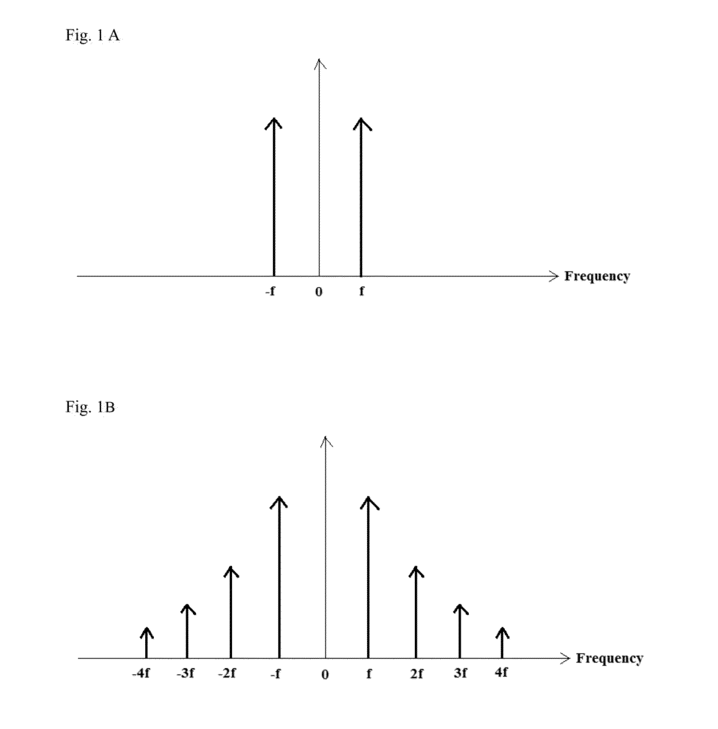
[0072]In the first example of the present disclosure, the fundamental frequency of the laser beam, which was amplitude modulated for pure sinusoidal modulation by using a loss modulation technique, was 500 kHz. By detecting the fundamental frequency and the harmonics of the fundamental frequency, 500 kHz and 1 MHz, images derived from single-photon and two-photon-absorption-induced photoacoustic effect were obtained.

[0073]As shown in FIG. 6, the pulsed light source 101 was a femtosecond laser (Tsunami Ti:Sapphire Laser, 800 nm femtosecond laser, pulse width ˜100 fs, repetition rate 80 MHz). Two acoustic optical modulators (AOMs) (Neos Technologies, 23080-3-.85-LTD) 102 were operated in CW mode and their modulation frequencies were adjusted by two controllers 1023 to be slightly different, 80.5 MHz and 81 MHz, respectively. A laser beam emitted from the pul...


PUM

PropertyMeasurementUnit
ultrasonic frequencyaaaaaaaaaa
center frequencyaaaaaaaaaa
penetration depthaaaaaaaaaa

Abstract

The present application discloses optical microscopy systems and related method that use modulation techniques and contrast agents to enable the systems to detect nonlinear photoacoustic signals with high spectrum sensitivity and frequency selectivity for imaging. A laser beam is amplitude modulated for pure sinusoidal modulation using either the loss modulation technique or the single light amplitude modulation technique. The sample used in the invention is an endogenous contrast agent by itself or is treated by at least one exogenous contrast agent to produce or enhance photoacoustic effect induced by multi-photon absorption. The modulated laser beam is focused via a focusing device onto a sample which absorbs multiple photons simultaneously and generates ultrasonic (acoustic) waves via nonlinear photoacoutic effect. The ultrasonic waves are received and transformed into electrical signals and the frequency signals within the electrical signals are detected and recorded to create images.

Description

BACKGROUND OF THE INVENTION[0001]1. Field of the Invention[0002]The field of the invention relates generally to optical microscopy systems based on multi-photon photoacoustic imaging. More particularly, the present disclosure is directed to optical microscopy systems that use modulation techniques and contrast agents to enable the systems to extract nonlinear photoacoustic signals for imaging with high spectrum sensitivity and frequency selectivity.[0003]2. Description of Prior Art[0004]Photoacoustic computed tomography (PACT) and photoacoustic microscopy (PAM) are emerging technologies allowing optical absorption contrast and ultrasonic resolution to be combined in one single modality to achieve high resolution imaging at a penetration depth that is beyond optical mean free path. However, the focus of the present disclosure is on PAM, rather than PACT.[0005]PAM can be categorized into acoustic resolution PAM (AR-PAM) and optical resolution PAM. (OR-PAM). AR-PAM weakly focuses a pul...

Claims


Application Information

Patent Timeline
Patent Type & Authority Applications(United States)
IPC IPC(8): G01N21/17
CPCG01N21/1702G01N2201/106G01N2201/0697G01N2201/06113G01N21/636G01N29/036G01N29/0654G01N29/2418
Inventor SUN, CHI-KUANGLAI, YU-HUNGCHANG, CHIEH-FENGLEE, SZU-YU
Owner NAT TAIWAN UNIV
Learn More