Magnetic inline filter

a technology of magnetic field and filter, which is applied in the direction of filtration separation, separation process, manufacturing tools, etc., can solve the problems of increasing running costs, clogging of filtration type filters, and requiring replacement work, etc., and achieves simple structure, high filtration ability, and intense magnetic field

Active Publication Date: 2015-06-18
SHOUNAN ENG
View PDF0 Cites 2 Cited by
  • Summary
  • Abstract
  • Description
  • Claims
  • Application Information

AI Technical Summary

Benefits of technology

[0018]In the structure of the magnetic inline filter of the present invention, the structure is simple, a magnetic field is intense, and a filtration ability is high. Since the magnetic field is intense, a...

Problems solved by technology

However, clogging easily occurs in the filtration type filter.
Running costs increase and manpower is required for replacement work.
However, since the disc-like permanent magnets are disposed only in the cylindrical space in the center, a magnetic field in a radiation direction is weak, magnetization of th...

Method used


Image

  • Magnetic inline filter
  • Magnetic inline filter
  • Magnetic inline filter

Examples


second embodiment

of the Magnetic Inline Filter

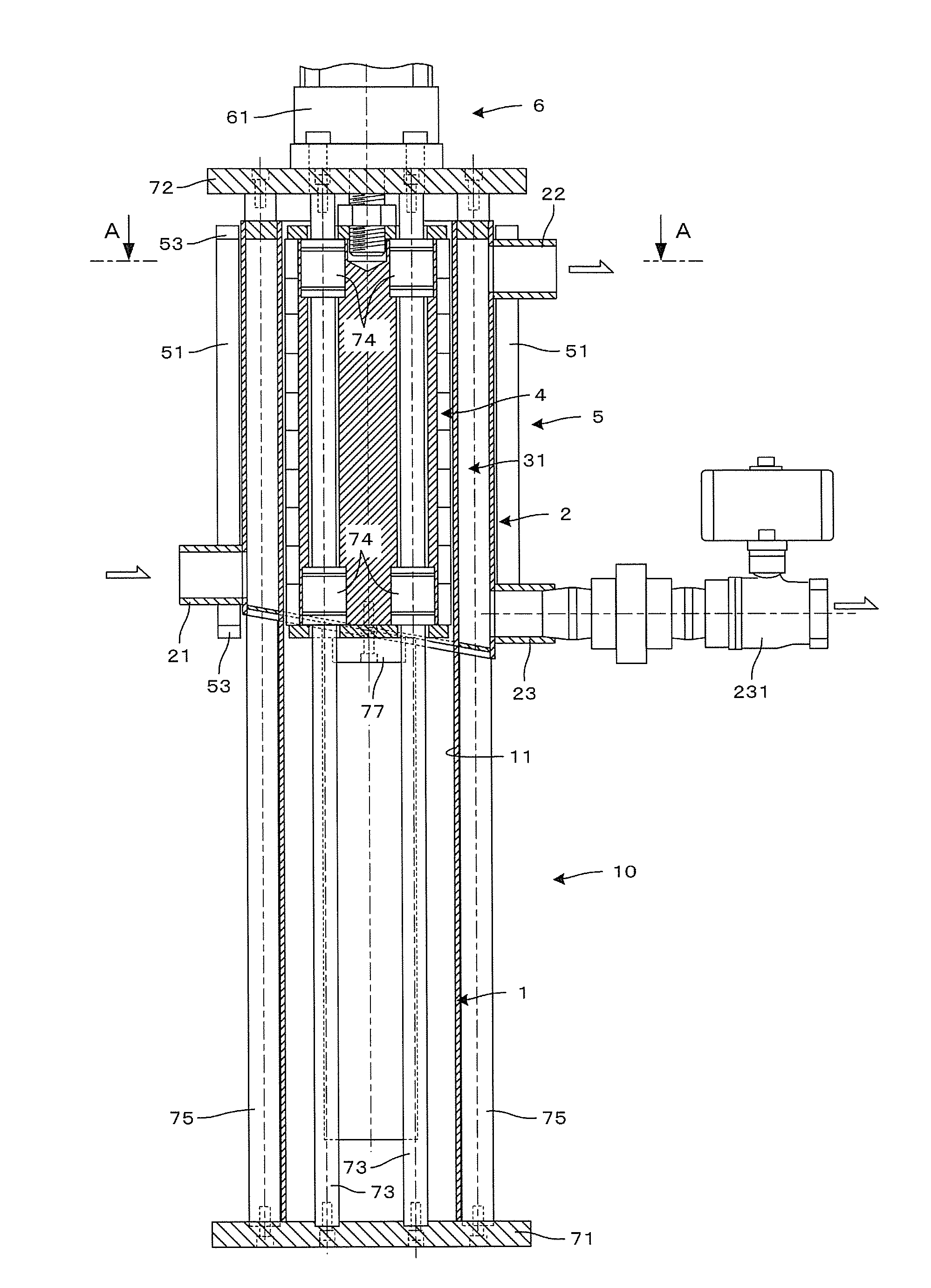
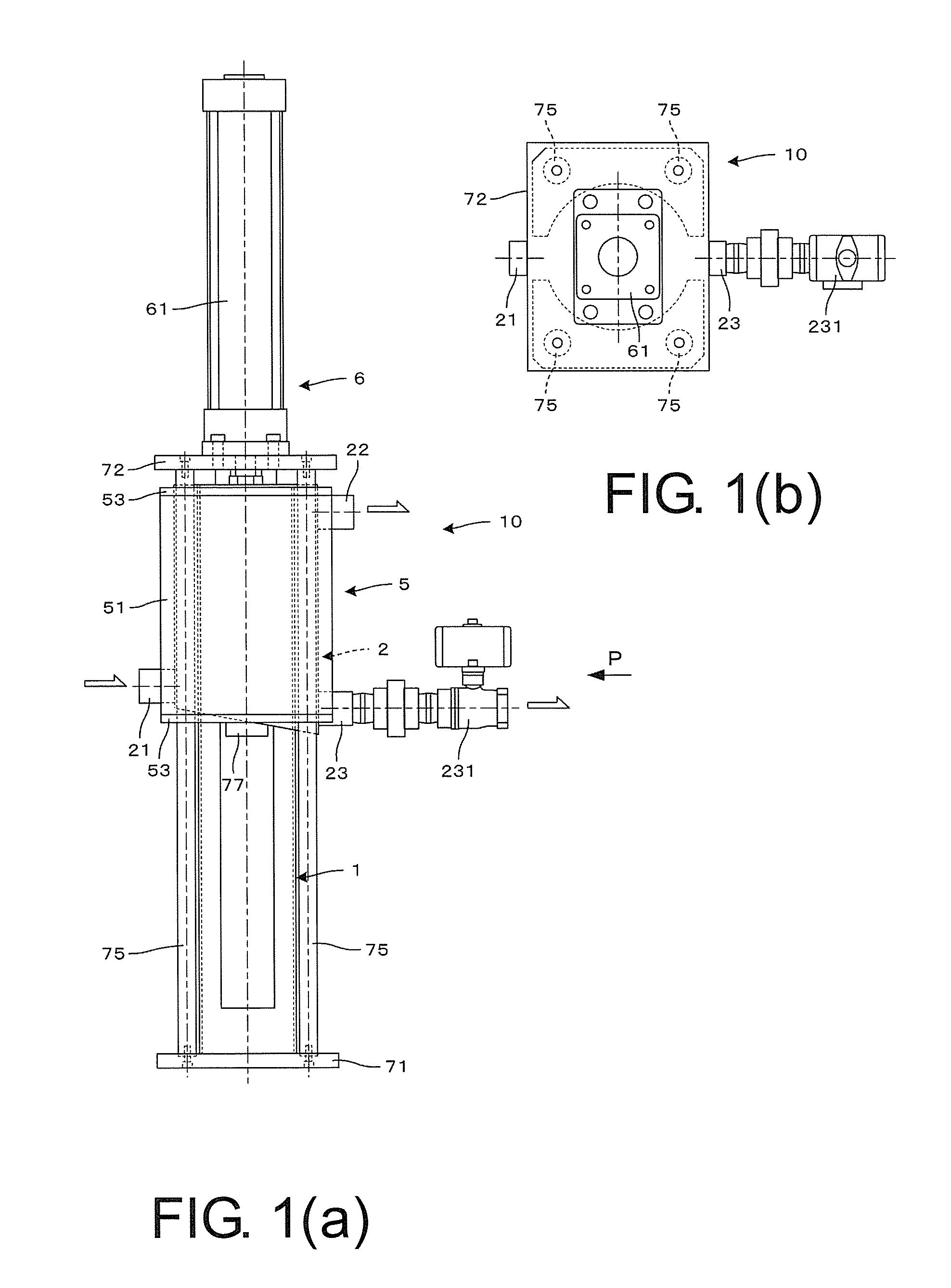
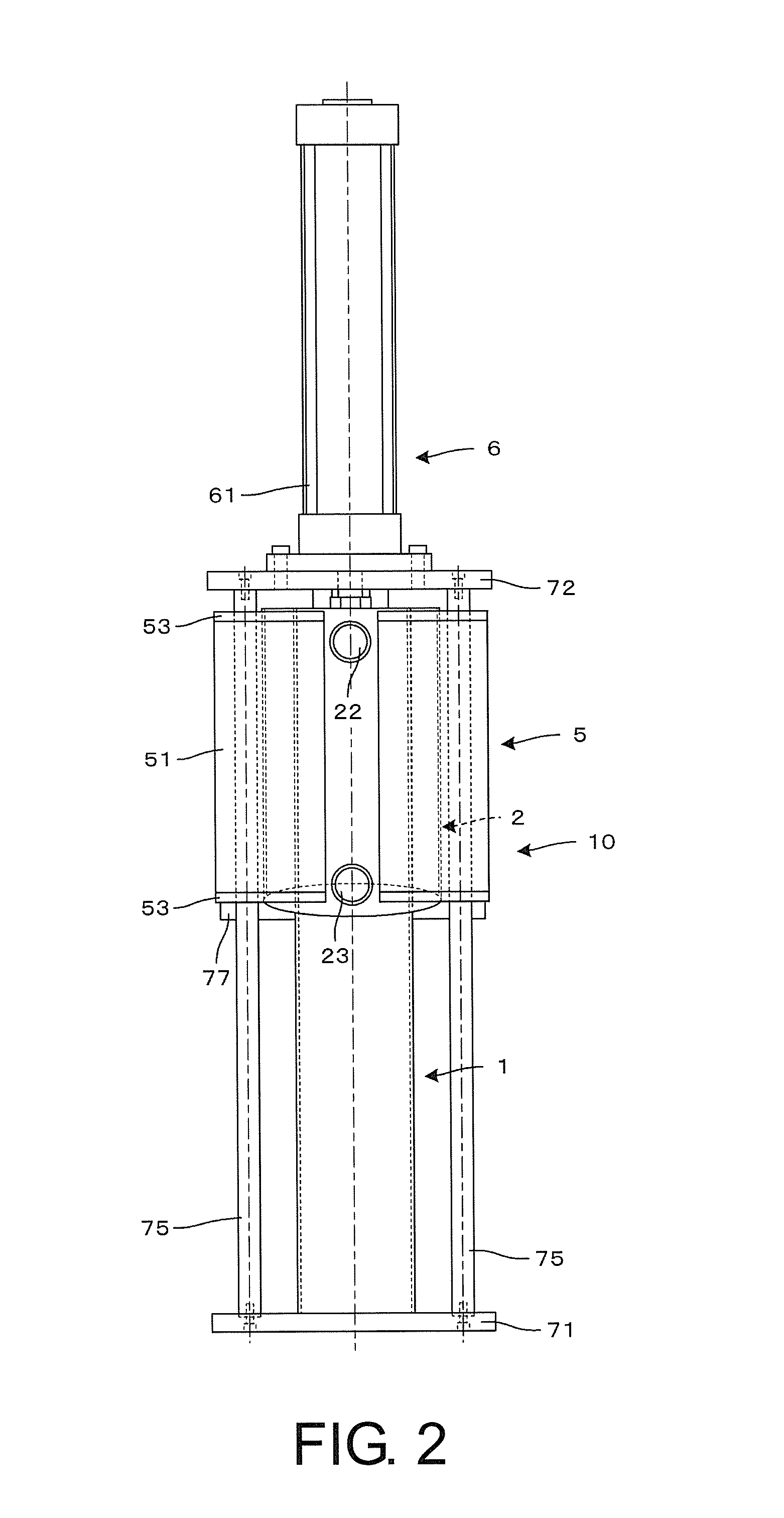
[0052]FIG. 12(a) is a diagram showing the magnetic inline filter 10 in a second embodiment of the present invention and equivalent to FIG. 10 in the first embodiment. FIG. 12(b) is an F-F sectional view of FIG. 12(a). The magnetic inline filter 10 in the second embodiment is a modification of the magnetic inline filter 10 in the first embodiment, and is an example in which an obstacle is formed in the space 31 to reduce the flow velocity of a part of a flow of a coolant. In the following explanation, only structural portions different from the structural portions in the first embodiment are explained. Redundant explanation is omitted. The same components are explained with the same numbers added to the components.

[0053]As shown in FIG. 12, the cylindrical body 3 of the magnetic inline filter 10 in the second embodiment of the present invention is a double pipe, in which the cylindrical inner pipe 1 and the cylindrical outer pipe 2 are coaxially disposed....

third embodiment

of the Magnetic Inline Filter

[0055]FIG. 13 is an overall front view showing the magnetic inline filter 10 in a third embodiment of the present invention and showing an example in which the magnetic inline filter 10 is attached to a coolant tank of a grinder. FIG. 14 is a plan view of FIG. 13. FIG.

[0056]15 is a right side view of FIG. 13. FIG. 16 is a piping diagram of FIG. 13. The magnetic inline filter 10 in the third embodiment is an example in which the magnetic inline filter 10 in the first embodiment is attached to a coolant tank of a grinder (a machine tool). In the following explanation, only structural portions different from the structural portions in the embodiments explained above are explained. Redundant explanation is omitted. The same components are explained with the same numbers added to the components.

[0057]As shown in FIG. 13 to FIG. 16, the magnetic inline filter 10 in the third embodiment of the present invention is fixed to the upper surface of a coolant tank 10...


PUM

PropertyMeasurementUnit
Lengthaaaaaaaaaa
Magnetic fieldaaaaaaaaaa
Circumferenceaaaaaaaaaa

Abstract

A magnetic inline filter is provided. A piston rod of a fluid cylinder is retracted to the top to locate an inner circumferential surface side magnet and an outer circumferential surface side magnet in filtration positions opposed to a space. In this state, a solenoid of a changeover valve is actuated to shut off a discharge port. A coolant is introduced into the space from an introduction port in the vicinity of the lower end of an outer pipe. Since a magnetic field in a radiation direction is intense, chips in the coolant are attracted to wall surfaces on both sides of the space and the coolant is filtrated. When the supply of the coolant is continued, the chips attracted to the wall surfaces are accumulated and bridged. As a result, since the coolant passes through gaps of the bridged chips, it is possible to perform precise filtration.

Description

TECHNICAL FIELD[0001]The present invention relates to a magnetic inline filter that removes magnetic bodies, which are foreign matters, in waste water with a filter. More particularly, the present invention relates to a magnetic inline filter that, to remove chips in a coolant supplied to a machining section of a machine tool, uses the chips themselves as a filter.BACKGROUND ART[0002]In a machine tool such as a grinder or a machining center, machining of a workpiece and cleaning of a jig are performed while a coolant is supplied to the workpiece in a machining section and the jig from a coolant tank. Chips of the machined workpiece and chips washed away from the jig are collected in the coolant tank together with the coolant, after large chips are collected by a chip conveyor. The collected coolant is filtrated by a filter disposed halfway in a piping route for supplying the coolant to the machining section and the like. Particulates mixed in the coolant are separated from the coola...

Claims


Application Information

Patent Timeline
IPC IPC(8): B03C1/12C02F1/48
CPCB03C1/12C02F1/488B03C2201/20C02F2201/002B03C2201/18C02F2201/48B03C1/0332B03C1/0335B03C1/286B03C1/288B24B55/03B01D35/06B03C1/02B23Q11/00C02F1/481
Inventor SAZAWA, MASAJI
Owner SHOUNAN ENG
Why Eureka
Try Eureka