Integrated electro-hydraulic brake system

a brake system and electrohydraulic technology, applied in the direction of brake action initiation, brake system, transportation and packaging, etc., can solve the problems of increasing weight, requiring space to be installed, and the application of an existing vacuum brake configured to amplify the pedal force of the driver while braking is inability to operate, so as to improve the safety of braking and facilitate installation in the vehicle. , the effect of simple configuration

Active Publication Date: 2015-06-18
HL MANDO CORP
View PDF14 Cites 10 Cited by
  • Summary
  • Abstract
  • Description
  • Claims
  • Application Information

AI Technical Summary

Benefits of technology

[0015]In view of the above-described problems, the present invention provides an integrated electro-hydraulic brake system that has a simple configuration to improve safe...

Problems solved by technology

In addition, since the fuel cell vehicles and the electric cars have no engine, an application of an existing vacuum brake configured to amplify a pedal force of the driver while braking is unable.
However, since each of the units 1, 2, and 3 constituting the electro-hydraulic brake system...

Method used


Image

  • Integrated electro-hydraulic brake system
  • Integrated electro-hydraulic brake system
  • Integrated electro-hydraulic brake system

Examples


Embodiment Construction

[0032]Hereinafter, exemplary embodiments of the present invention will be described in detail with reference to the accompanying drawings. Moreover, terms and words used in this specification and claims should not be interpreted as limited to commonly used meanings or meanings in dictionaries and should be interpreted with meanings and concepts which are consistent with the technological scope of the invention based on the principle that the inventors have appropriately defined concepts of terms in order to describe the invention in the best way. Therefore, since the embodiments described in this specification and configurations illustrated in drawings are only exemplary embodiments and do not represent the overall technological scope of the invention, it is understood that the invention covers various equivalents, modifications, and substitutions at the time of filing of this application.

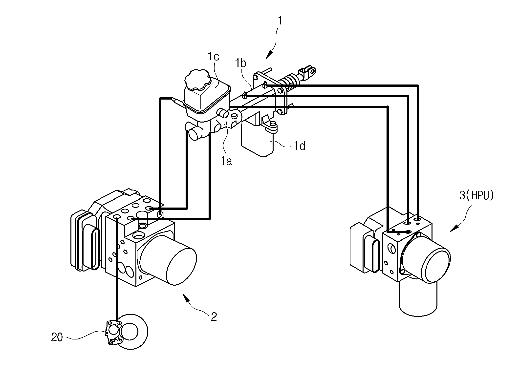
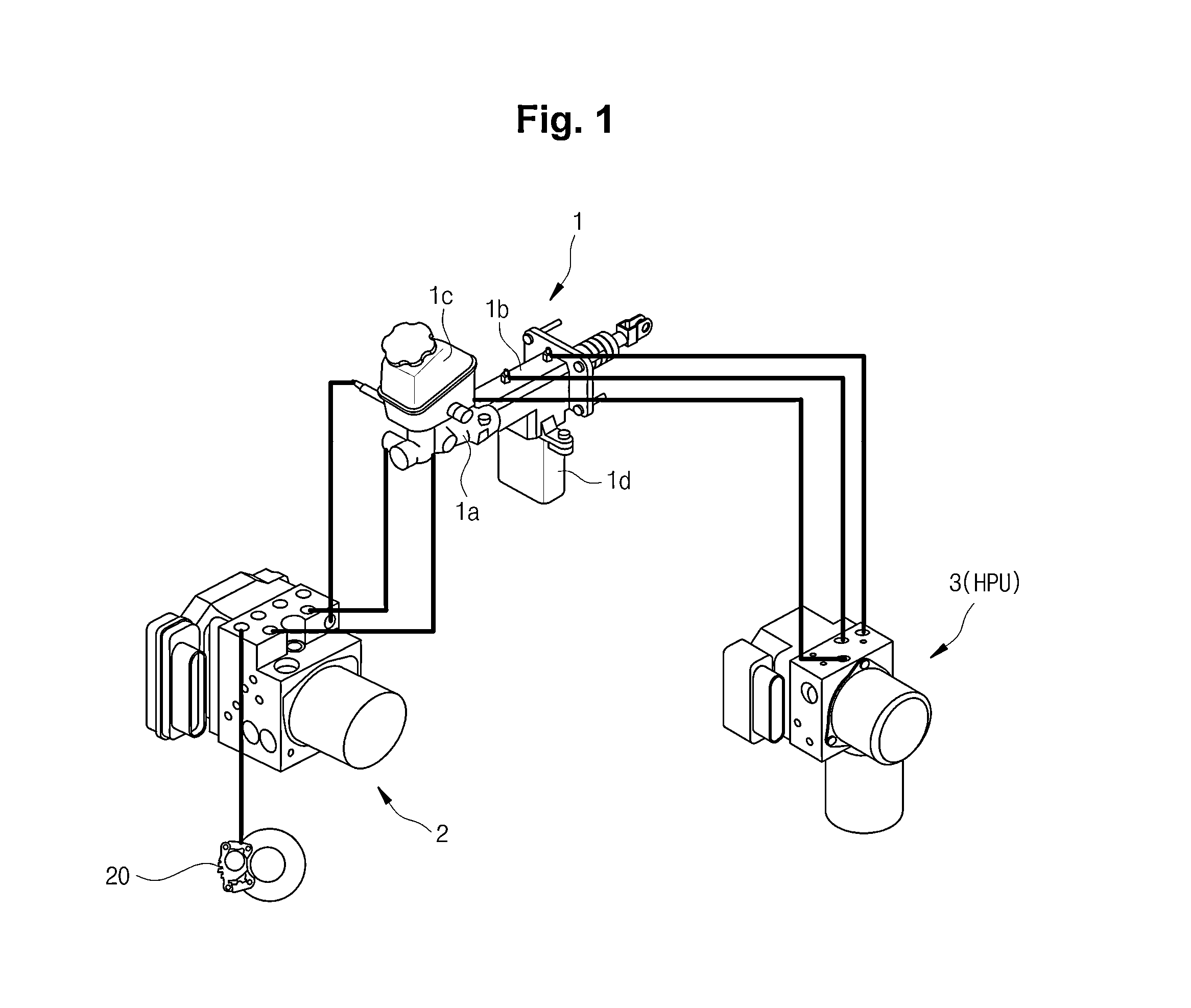
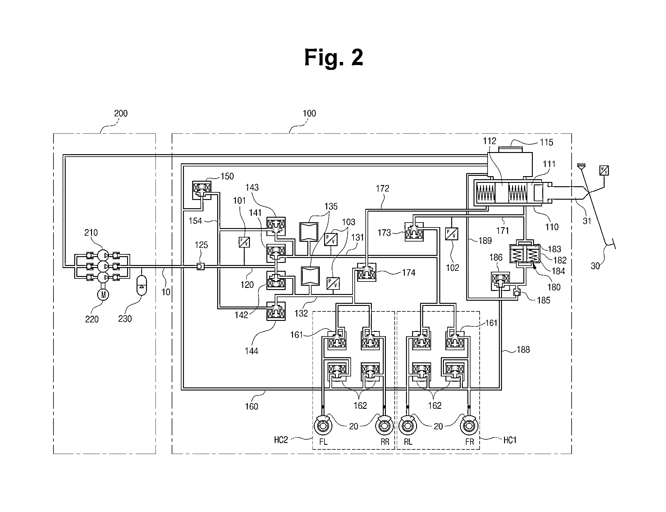
[0033]FIG. 2 is a hydraulic circuit diagram illustrating an integrated electro-hydraulic brake ...


PUM


Abstract

There is provided an integrated electro-hydraulic brake system. The integrated electro-hydraulic brake system include a power source unit including an accumulator configured to store a pressure of a predetermined level, a pump configured to suck oil from a reservoir and discharge the oil to the accumulator in order to generate a pressure in the accumulator, and a motor configured to drive the pump; and an integrated hydraulic control device including a master cylinder having two hydraulic circuits and configured to generate a hydraulic pressure, a reservoir connected above the master cylinder and configured to store oil, an in-valve and an out-valve configured to control a pressure delivered from the accumulator to a wheel cylinder installed in each wheel, a shut off valve configured to control a fluid pressure delivered from the master cylinder to the wheel cylinder, a pedal simulator connected to the master cylinder and configured to provide a reaction force of a brake pedal, and a simulation valve installed in a rear end of the pedal simulator, wherein the power source unit is provided as a separate unit in order to isolate operating noises, and the integrated hydraulic control device and the power source unit are connected by an external pipe, and the out-valve is provided as a normally open type-solenoid valve that is used at low current ranges, normally maintains an open state in order to reduce heat generation, but is closed when a close signal is received, compared to a normally close type-solenoid valve that normally maintains a close state.

Description

CROSS-REFERENCE TO RELATED APPLICATION[0001]This application claims the benefit of Korean Patent Application No. P2013-0155090, filed on Dec. 13, 2013 in the Korean Intellectual Property Office, the disclosure of which is incorporated herein by reference.BACKGROUND[0002]1. Field[0003]Embodiments of the present invention relate to an electro-hydraulic brake system, and more specifically, to an integrated electro-hydraulic brake system that provides an actuator including a master cylinder, a pedal simulator, and the like, electronic stability control (ESC), and a hydraulic power unit (HPU) as a single unit.[0004]2. Description of the Related Art[0005]Recently, in order to improve fuel efficiency and reduce exhaust fumes, the development of hybrid vehicles, fuel cell vehicles, electric cars, and the like has been actively progressing. A brake device, that is, a brake device of an automotive brake system, is necessarily installed in such vehicles. Here, the automotive brake device refer...

Claims


Application Information

Patent Timeline
IPC IPC(8): B60T13/14B60T13/68B60T7/04
CPCB60T13/145B60T13/686B60T7/042B60T8/368B60T8/4081B60T13/146B60T13/662B60T11/16B60T11/232B60T13/12
Inventor KIM, HYUN-JUN
Owner HL MANDO CORP
Why Eureka
Try Eureka