
Temperature limiter for fluidic systems

a technology of temperature limiter and fluidic system, which is applied in the safety instruments, lighting and heating apparatus, etc., can solve the problems of loss of flow, overheating of solar thermal heating systems, and heat supply from solar collectors or collectors is greater than heat load or demand, and achieves cost savings, simple, and inexpensive. , the effect of reducing the cost of installation

Inactive Publication Date: 2015-06-18
PO BOX 32598
View PDF12 Cites 9 Cited by
  • Summary
  • Abstract
  • Description
  • Claims
  • Application Information

AI Technical Summary

Benefits of technology

The T-clip is a new device that helps control the temperature of fluids in a system, preventing them from getting too hot or too cool. This can be especially useful in solar thermal systems, where overheating can cause damage or reduce efficiency. The T-clip automatically adjusts to the fluid's needs and works with existing valves and piping to provide reliable control and prevent damage to the system.

Problems solved by technology

Many solar thermal heating systems suffer from overheating problems, including the loss-of-load problem, the over-supply problem, and the loss-of-flow problem.
Loss-of-load and over-supply problems involve a mismatch in which the heat supply from the solar collector or collectors is greater than the heat load or demand.
The loss-of-flow problem involves a loss or degradation of system fluid flow usually due to pump stoppage or slowing.
Overheating of the fluid experiencing these problems sometimes leads to fluid breakdown, boiling and overpressurization in the solar collector(s), and consequently to damage to the solar collector(s) and other parts of the system.
However, closed-loop solar thermal systems do not have a solid, proven means of dealing with overheating in all situations.
A classic loss-of load solar-hot-water problem typically arises when a family goes on vacation in the summer without putting the solar system into vacation mode.
With the water in a hot water storage tank already hot, and no calls for hot water, the system may overheat even with the system pump on because the solar collectors continue to add heat to the system which does not need it.
Fluid breakdown, boiling and over-pressurization of the fluid in the solar collector usually follow, with accompanying damage to the solar collector(s), the solar thermal system and / or to the fluid itself in the case of antifreeze solutions.
If designers were to design a system with more solar collector area for more hot water in winter, the system could produce an over-supply of heat at times in the summer, thus potentially leading to overheating and consequent fluid breakdown, boiling and over-pressurization of the fluid, and accompanying damage as described above.
When the system fluid pump stops or slows down or for any flow degradation condition, the stagnant or nearly stagnant fluid in the solar collector on a sunny day may increase in temperature to the point where it breaks down and / or boils, again causing damage.
. . in the event that fluid in the solar energy absorber vaporizes, the fluid is forced out of the solar energy absorber and into the pressure vessel.” This protection system fails to prevent boiling before it starts.
The allowed boiling may damage the system or fluid in the system.
This protection system works only for flat plate solar collectors, and compromises the thermal integrity of the solar collector with openings and mechanical dampers which wear and eventually fail to close completely or properly.
This system only addresses a loss of flow, only works for a pressurized system, and by itself fails to prevent boiling.
This damper system works only for flat plate solar collectors, and compromises the thermal integrity of the solar collector with openings and mechanical dampers which wear and eventually fail to close completely or properly.
This system is expensive and complex.
The system does not work for the loss-of-load problem, for the over-supply problem, for the partial-system-flow situation, nor any pump-on failure mode.
“When the fluid pump is off, the working fluid circulates through the thermosyphon cooling loop, but when the fluid pump is on, the working fluid circulates through a heating loop.” Overheating may still occur with this system in pump-on failure modes.
In addition, because the cooling assembly is “integral with” the back side of the solar collector, the system is not low-profile when flush-mounted to a roof.
This wastes energy, and results in longer times to bring the storage tank up to temperature.
These systems are generally complex, expensive and difficult to service and to diagnose when troubles arise.
These systems risk allowing tank fluid temperatures to get too high, and waste water by discharging hot water down the drain and injecting cold water.
Such systems are potentially unsafe and wasteful of energy and water.
Solar thermal systems retrofit installations are infrequently done because of the expense and complexity of the installation.
Much of the complexity and expense come from the lack of an available heat dump or the difficulty and expense of piping to a heat dump.
When they are done, such retrofit installations typically are undersized to prevent overheating problems.
Use of renewable energy in solar thermal systems is hampered by the complexity and expense of installation and is underutilized by undersizing.
These valve arrangements do not provide in-line cooling, and require an external source of cooling.
Such a cold return is not available in a solar thermal system and many other fluidic systems.
Such a cold source is not available in a solar thermal system.
However, typically the temperature of the coolant coming from the radiator and reentering the engine is unregulated.
This may produce cold sections in the engine and lead to increased wear.
This system cools the oil when it becomes too hot, but does not control the amount of cooling as flow is simply directed into a heat dissipator without regard as to the fluid temperature exiting the heat dissipator.
This results in overcooling the engine oil, especially in very cold climates.
When a high temperature issue arises and is detected, it is usually too late, with the result being that some hydraulic component malfunctions or fails.
Current systems fail to prevent or mitigate high temperature conditions.
Most current cooling systems for machines that use these fluids fail to limit temperature or maintain a constant fluid temperature.
In addition, current fluidic systems without electronic controls don't adjust to changing conditions such as ambient temperature, heat transfer rate from the heat dissipator, flow rate change from pump degradation, flow path blockage, or fluid temperature change.
Adding electronic controls adds to the complexity of fluidic systems and adds extra expense.

Method used


Image

  • Temperature limiter for fluidic systems
  • Temperature limiter for fluidic systems
  • Temperature limiter for fluidic systems

Examples


Embodiment Construction

1. Definitions

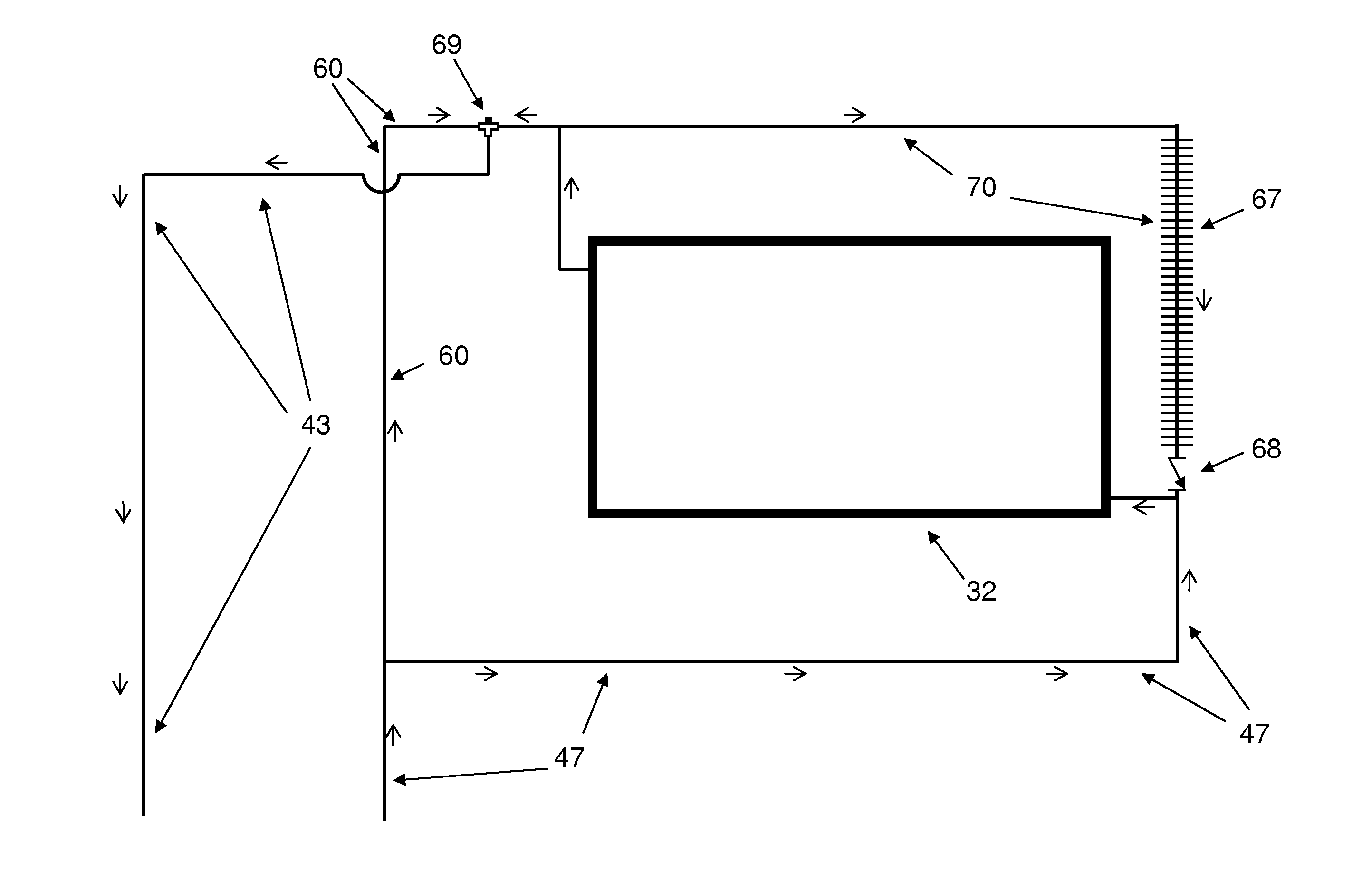
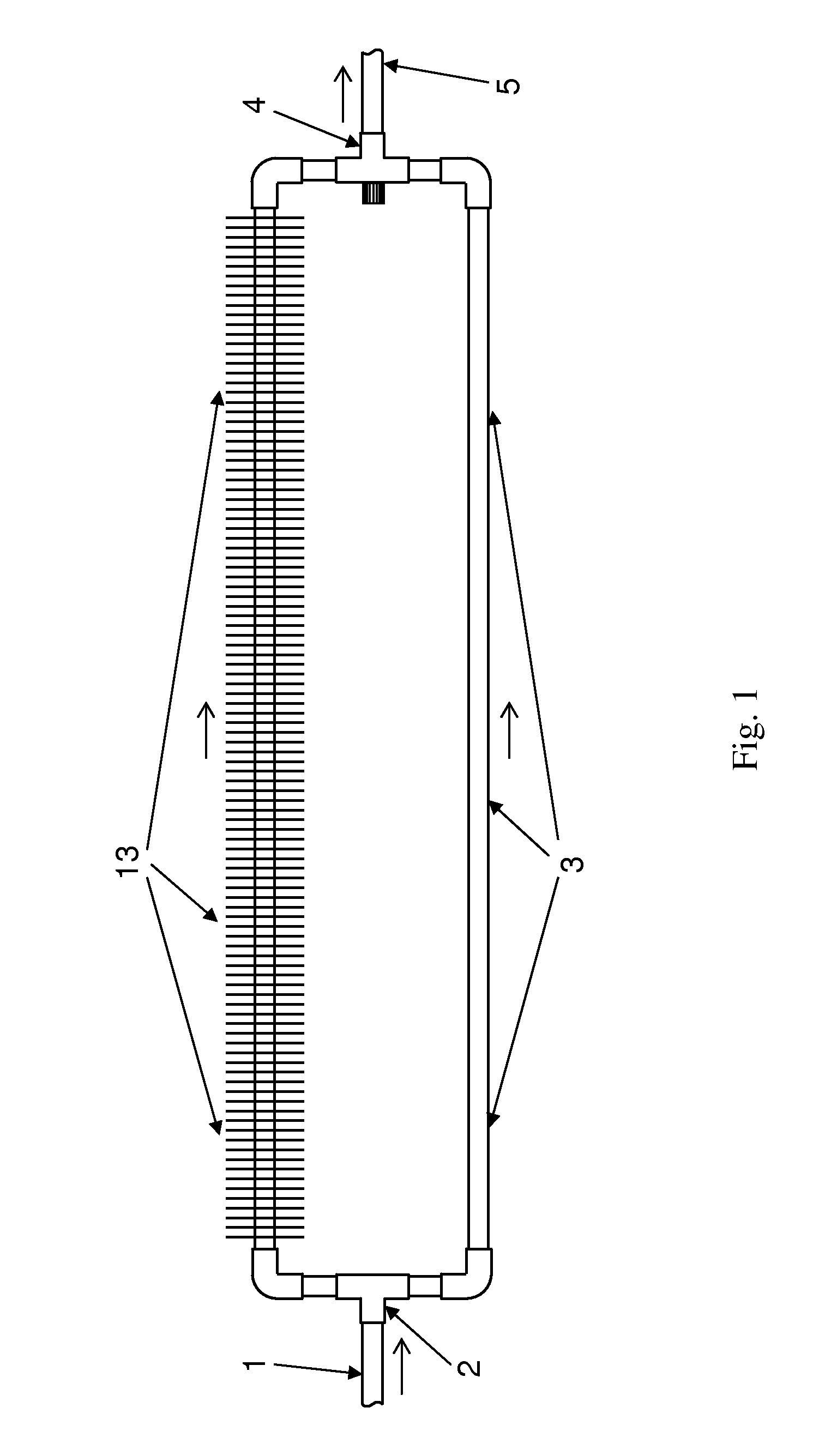
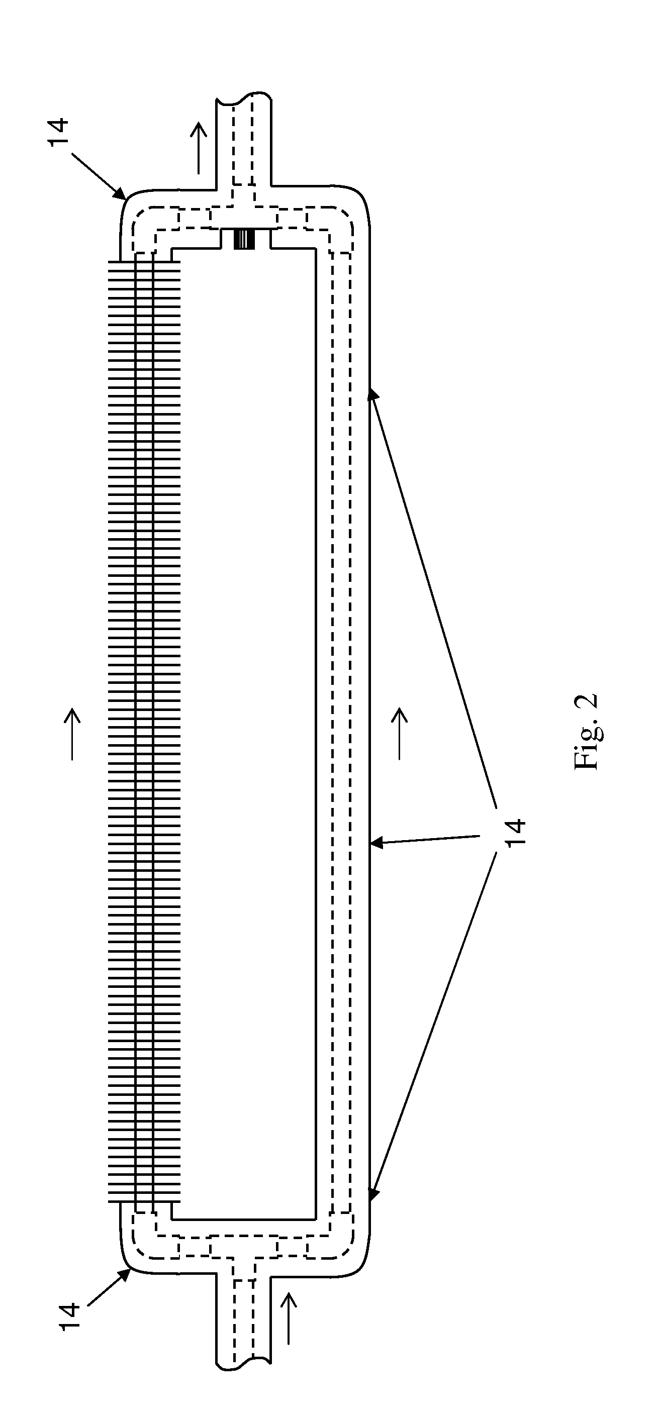
[0068]T-clip. “T-clip” is defined, herein, as the name of the present invention, a flowing-fluid-cooling, temperature-limiting apparatus for use in fluidic systems.

[0069]Fluidic system. “Fluidic system” is defined, herein, as a system comprising fluid, components and piping that come in contact with the fluid, and components for monitoring or controlling the system. A fluidic system may be open or closed. A fluidic system may be a subsystem of a larger fluidic system.

[0070]Piping. “Piping” is defined, herein, as a system of joined and fluid-coupled fluidic conduits through which fluid may flow from one component of a fluidic system to another. Piping includes, but is not limited to, pipes, tubes, hoses, manifolds, connectors, such as a tee or elbow, and the means for joining them to each other and to components. Piping may be rigid or flexible. Piping connections may be welded, bolted-flange, threaded, soldered, union-joint, pressure-fit, fitting-type, compression-type...


PUM


Abstract

The present invention limits fluid temperature at a point in a fluidic system to below a predetermined temperature by cooling the fluid when needed and without requiring a separate cold fluid source. The present invention “clips” the temperature of the fluid at a point in the system to within a temperature range and prevents overcooling the fluid. When the fluid temperature is below the temperature range, the temperature of the fluid is unchanged as it passes through the apparatus of the present invention. The present invention may operate without external power, can function in any orientation, and works for unpressurized and pressurized systems. The present invention has application in the areas of solar thermal energy systems, fluid tanks, engine oil and coolant systems, transmission fluid systems, hydraulic systems, machining fluid systems, and cutting fluid systems, among others.

Description

CROSS REFERENCE TO RELATED APPLICATIONS[0001]This application is a Continuation In Part of U.S. patent application Ser. No. 13 / 556,172 filed Jul. 23, 2012, by the present inventor, which is incorporated by reference. This application is also a national phase application of PCT / US13 / 50745, filed Jul. 16, 2013, by the present inventor, which is also incorporated by reference.BACKGROUND OF THE INVENTION[0002]1. Field of the Invention[0003]The present invention relates to fluidic systems, both closed and open systems, in which fluid temperature control at a point in the system is necessary or desirable. The present invention prevents fluid temperature from exceeding a predetermined set temperature at a point in the piping of a system, by cooling the flow in a controlled manner when required. One of the applications of the present invention is in the area of renewable energy, specifically solar thermal systems for water heating and space heating. Other applications include, but are not l...

Claims


Application Information

Patent Timeline
Patent Type & Authority Applications(United States)
IPC IPC(8): F24J2/46F24J2/24F24J2/44G05D23/13F24S10/70
CPCF24J2/4625F24J2/44F24J2/24G05D23/13F28D2021/0029F24S40/55G05D23/134Y02E10/40
Inventor WEHNER, THOMAS RICHARD
Owner PO BOX 32598
Learn More