Feed ratio control for hter

a technology of feed ratio and hter, which is applied in the direction of chemical/physical/physical-chemical processes, chemical apparatus and processes, organic chemistry, etc., can solve the problems of failure due to metal dusting, corrosion by metal dusting, and significant reduction of the affinity of hot metal surfaces with metal dusting

Inactive Publication Date: 2015-06-25
HALDOR TOPSOE AS
View PDF1 Cites 10 Cited by
  • Summary
  • Abstract
  • Description
  • Claims
  • Application Information

AI Technical Summary

Problems solved by technology

Doing a pinch point analysis on this will typically lead to the conclusion that the sensible heat in the gas from the reformer can be utilised better, as the temperature differ-ence in the hot end typically is in the range from 650-750° C. However, due to the corrosion phenomenon known as metal dusting, it is a challenge to design the heat exchange apparatus in such a way that plant reliability is not jeopardised.
Even in the waste heat boilers used in traditional synthesis gas plants where the possibility of hot metal surfaces with affinity for metal dusting is significantly reduced due to relatively low temperature and high heat transfer coefficients on the steam / water side, failures due to metal dusting have been seen.
A major challenge in connection with Heat Exchange Reformers heated by reformed process gas is corrosion by metal dusting, which typically can occur in the temperature range from 400-800° C. in atmospheres rich in CO and / or hydrocarbons.
However, at a certain temperature, say 400-450° C., the reaction rate is so low that insignificant corrosion takes place in practise.
However, operation under conditions with affinity for carbon formation requires extensive testing prior to use in commercial units, and Topsøe is continuously testing materials and operating conditions in order to map metal dusting attacks in the laboratory and has an extensive collaboration with leading companies de-veloping special alloys.
The operating conditions for this reformer are relatively severe with respect to metal dusting due to the high temperature and low steam-to-carbon ratio.
The first tube bundle was in operation for more than seven years and the metal dusting corrosion was within the expected rate and not the reason for replacement of the tube bundle.
Over-estimating the heat transfer and catalyst activity will result in an apparatus which cannot meet the design capacity, but applying a “design margin” is not the solution as too good heat transfer and / or catalyst activity may result in critical operation with metal dusting attacks.

Method used


Image

  • Feed ratio control for hter
  • Feed ratio control for hter
  • Feed ratio control for hter

Examples


Embodiment Construction

[0065]By the present invention, a method is disclosed in which a metal resistant to metal dusting is used at a distance from the inlet of the heat exchange reformer, and in which such distance is calculated from the steam to carbon ratio, effluent outlet temperature and hydrocarbon flow of the main reformer, as well as the steam to carbon ratio and hydrocarbon flow rate of the heat exchange reformer.

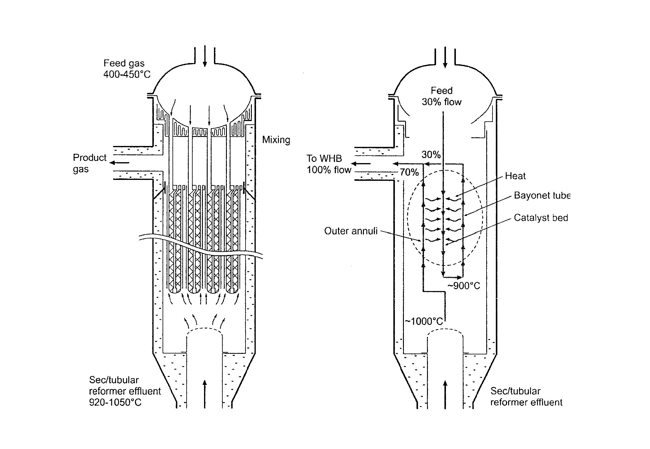
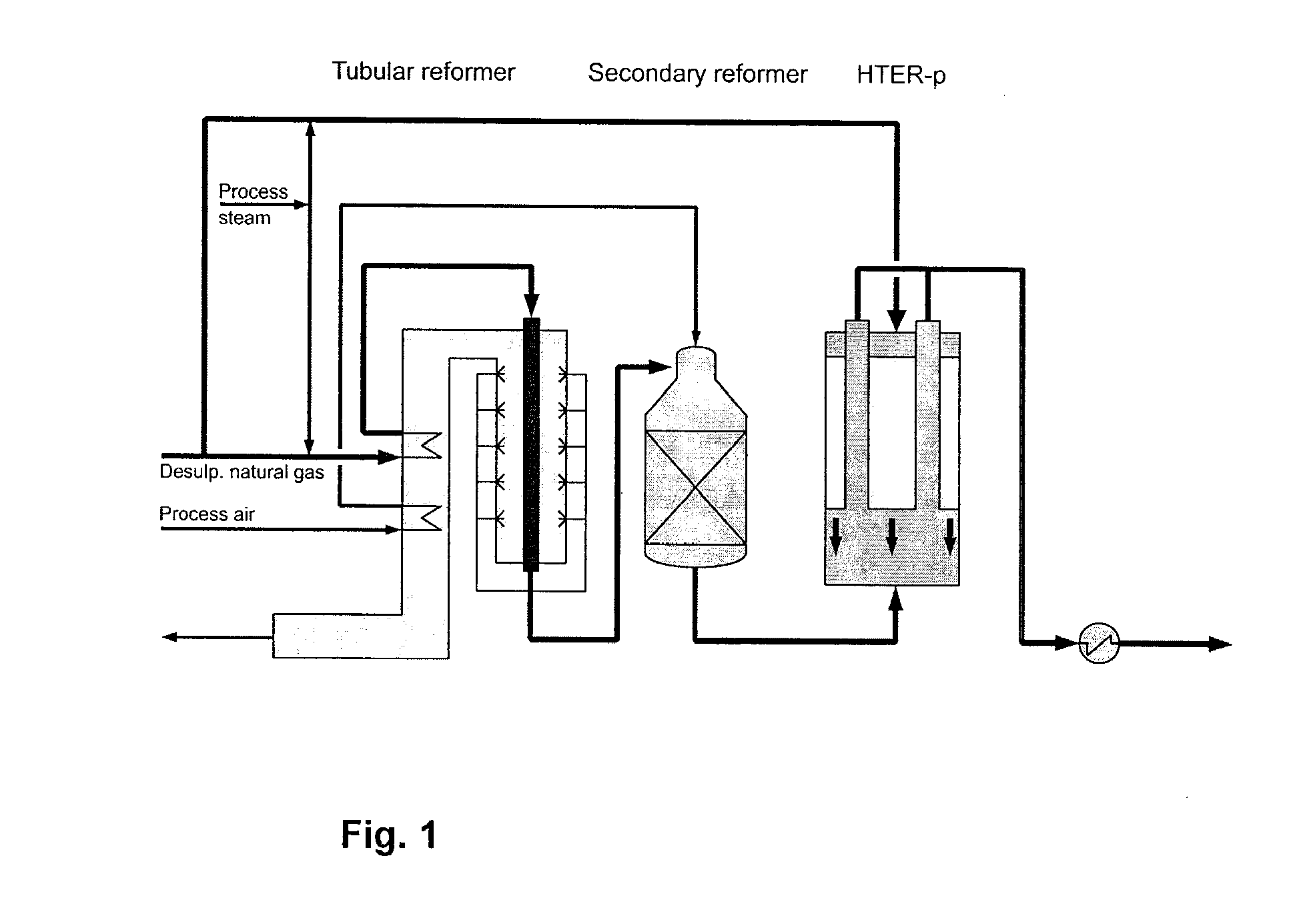
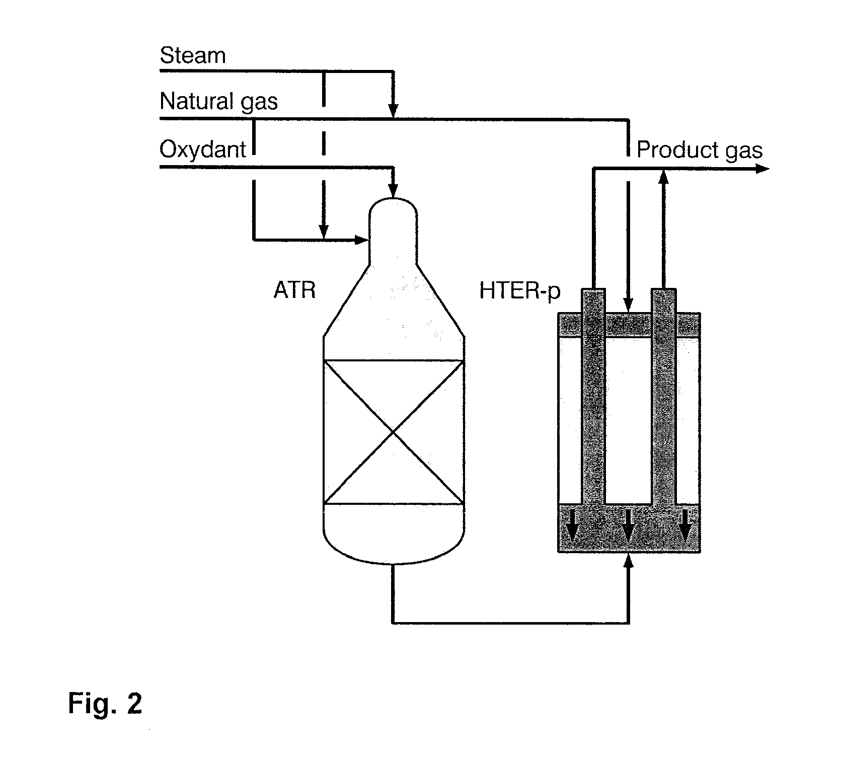
[0066]The present invention relates to a Heat Exchange Reformer (HER) arranged to be part of a synthesis gas production unit, said synthesis gas production unit comprising a Main Reforming Unit (MRU) and said Heat Exchange Reformer (HER). In operation, the effluent from the MRU is arranged so as to provide heat to the HER, and wherein a hydrocarbon feedstock is arranged so as to pass in parallel through both the MRU and the HER. The invention thus provides:[0067]a. an MRU hydrocarbon feed having an MRU steam-to-carbon ratio (MRUS / C), an effluent outlet temperature (TMRU) and a MRU hydroc...


PUM

PropertyMeasurementUnit
temperatureaaaaaaaaaa

Abstract

The invention provides a Heat Exchange Reformer (HER) arranged to be part of a synthesis gas production unit and comprising at least a first and a second metal in order to minimise metal dusting. The invention moreover relates to a method for improved thermal control in a Heat Exchange Reformer (HER) and a computer readable storage medium. The invention provides improved thermal control and reduced metal dusting of the Heat Exchange Reformer.

Description

[0001]This is a continuation-in-part of application Ser. No. 14 / 151,435, filed Jan. 9, 2014, now abandoned, the entire disclosure of which is herein incorporated by refer-ence.BACKGROUND OF THE INVENTION[0002]In connection with synthesis gas production by steam reforming, high temperatures are required in order to achieve a feasible conversion of the hydrocarbons into synthesis gas.[0003]In the traditional synthesis gas plants, the sensible heat in the synthesis gas has been used for steam generation. Doing a pinch point analysis on this will typically lead to the conclusion that the sensible heat in the gas from the reformer can be utilised better, as the temperature differ-ence in the hot end typically is in the range from 650-750° C. However, due to the corrosion phenomenon known as metal dusting, it is a challenge to design the heat exchange apparatus in such a way that plant reliability is not jeopardised. Even in the waste heat boilers used in traditional synthesis gas plants ...

Claims


Application Information

Patent Timeline
Patent Type & Authority Applications(United States)
IPC IPC(8): C01B3/34B01J19/02
CPCC01B3/34B01J19/02C01B2203/142C01B2203/0205C01B2203/0844B01J2219/0277B01J8/062B01J8/067B01J8/008B01J8/025B01J8/0257B01J8/0278B01J8/0285C01B3/382B01J2208/00212B01J2219/00006B01J2219/00038B01J2219/0004C01B2203/0233C01B2203/0244C01B2203/0283C01B2203/043C01B2203/0805C01B2203/0816C01B2203/1241C01B2203/1247C01B2203/1258C01B2203/141C01B2203/143Y10T29/4935
Inventor JENSEN, MARTIN F.HANSEN, CLAUS F.THOMSEN, SOREN G.
Owner HALDOR TOPSOE AS
Why Eureka
Try Eureka